Difference between revisions of "RPI-MDI"
Jump to navigation
Jump to search
Blwikiadmin (talk | contribs) |
Blwikiadmin (talk | contribs) |
||
| Line 33: | Line 33: | ||
[[File:RPI-MDI-Front.png]] | [[File:RPI-MDI-Front.png]] | ||
| − | + | * Marking is nearest pin 1 | |
| − | + | ||
| − | + | * Pin 1 is a square pin | |
| − | + | ||
| − | + | === J1 - Servo Output 1 - PWM_LED0 pin on IC === | |
| − | + | ||
| − | |||
| − | Marking is nearest pin 1 | ||
| − | Pin 1 is a square pin | ||
| − | J1 - Servo Output 1 - PWM_LED0 pin on IC | ||
J1-1 = GND | J1-1 = GND | ||
J1-2 = VCC (+5V) | J1-2 = VCC (+5V) | ||
J1-3 = PWM output line | J1-3 = PWM output line | ||
| − | J2 - Servo Output 2 - PWM_LED6 pin on IC | + | |
| + | === J2 - Servo Output 2 - PWM_LED6 pin on IC === | ||
| + | |||
J2-1 = GND | J2-1 = GND | ||
J2-2 = VCC (+5V) | J2-2 = VCC (+5V) | ||
J2-3 = PWM output line | J2-3 = PWM output line | ||
| − | J3 - Servo Output 3 - PWM_LED7 pin on IC | + | |
| + | === J3 - Servo Output 3 - PWM_LED7 pin on IC === | ||
| + | |||
J3-1 = GND | J3-1 = GND | ||
J3-2 = VCC (+5V) | J3-2 = VCC (+5V) | ||
J3-3 = PWM output line | J3-3 = PWM output line | ||
| − | J4 - Switch Input 1 - GPIO_25 | + | |
| + | === J4 - Switch Input 1 - GPIO_25 === | ||
| + | |||
J4-1 = GPIO_25 | J4-1 = GPIO_25 | ||
J4-2 = GND | J4-2 = GND | ||
| − | J5 - Switch Input 2 - GPIO_4 | + | |
| + | === J5 - Switch Input 2 - GPIO_4 === | ||
| + | |||
J5-1 = GPIO_4 | J5-1 = GPIO_4 | ||
J5-2 = GND | J5-2 = GND | ||
| − | J6 - Switch Input 3 - GPIO_22 | + | |
| + | === J6 - Switch Input 3 - GPIO_22 === | ||
| + | |||
J6-1 = GPIO_22 | J6-1 = GPIO_22 | ||
J6-2 = GND | J6-2 = GND | ||
| − | Power/capacitance connector | + | |
| + | === Power/capacitance connector === | ||
| + | |||
This is a three pin L shaped connector located in the following corner of the board. | This is a three pin L shaped connector located in the following corner of the board. | ||
| − | RPI-MDI-ExtDC-Pads.png | + | [[File:RPI-MDI-ExtDC-Pads.png]] |
| − | + | # Ground | |
| − | + | # Servo +5V | |
| − | + | # +5V-Raspberry Pi | |
== Schematic == | == Schematic == | ||
Revision as of 20:30, 26 January 2020
Contents
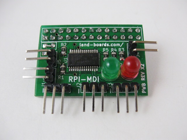
Raspberry Pi Servo Card
Features
- Raspberry Pi daughtercard
- Fits on "old" Model B or "new" Model B Plus board
- Three axis Servo PWM outputs (Servos not included)
- Two PWM Controlled LEDs
- I2C controlled 16-channel PWM controller PCA9685
- 5 channels used as above (Three Servo outputs, 2 LED outputs)
- PWM controller has internal built-in clock generator - no refresh required
- Even though the Raspberry Pi has 3.3V I/O, the PWM outputs run at 5V - compatible with typical servos
- Three switch inputs with on-board pull-ups which can be used as GPIO lines
- 3X of 10 uF SMT capacitors on rear of board for PWM/Servo noise reduction
- Right angle connectors for Low Profile
- Recessed connectors for side connectors for smallest form factor
- Very small size 1.4" x 1"
- Jumper to use 5V from Raspberry Pi (if your power supply has sufficient capacity) or pads for external power or additional capacitance if needed
- Python PWM - Adafruit driver
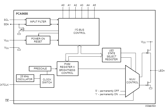
PCA9685 Block Diagram
Connectors
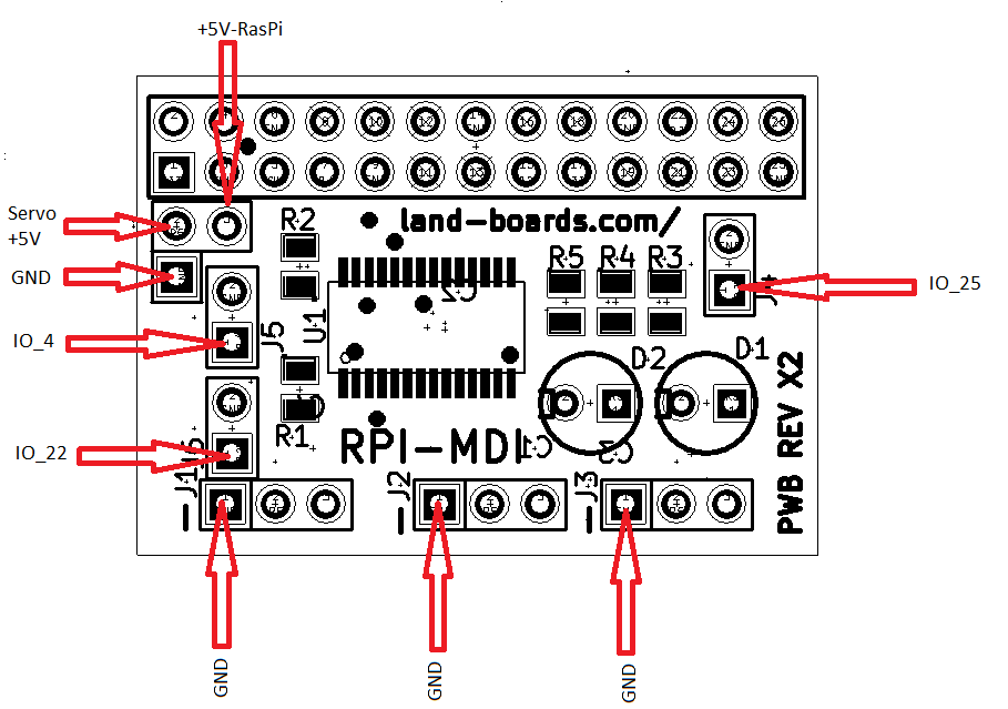
- Marking is nearest pin 1
- Pin 1 is a square pin
J1 - Servo Output 1 - PWM_LED0 pin on IC
J1-1 = GND J1-2 = VCC (+5V) J1-3 = PWM output line
J2 - Servo Output 2 - PWM_LED6 pin on IC
J2-1 = GND J2-2 = VCC (+5V) J2-3 = PWM output line
J3 - Servo Output 3 - PWM_LED7 pin on IC
J3-1 = GND J3-2 = VCC (+5V) J3-3 = PWM output line
J4 - Switch Input 1 - GPIO_25
J4-1 = GPIO_25 J4-2 = GND
J5 - Switch Input 2 - GPIO_4
J5-1 = GPIO_4 J5-2 = GND
J6 - Switch Input 3 - GPIO_22
J6-1 = GPIO_22 J6-2 = GND
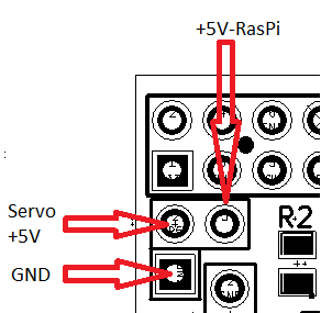
Power/capacitance connector
This is a three pin L shaped connector located in the following corner of the board.
- Ground
- Servo +5V
- +5V-Raspberry Pi
Schematic
Drivers/Example Code
- Github repo - Driver code


