Difference between revisions of "DTE"
Jump to navigation
Jump to search
Blwikiadmin (talk | contribs) |
Blwikiadmin (talk | contribs) |
||
| Line 27: | Line 27: | ||
# RTS (out) | # RTS (out) | ||
# VCC | # VCC | ||
| + | # CTS (in) | ||
| + | # Tx (out) | ||
# RX (in) | # RX (in) | ||
| − | |||
| − | |||
== DTE Assembly Sheet == | == DTE Assembly Sheet == | ||
* [[DTE Assembly Sheet]] | * [[DTE Assembly Sheet]] | ||
Revision as of 16:27, 22 February 2020
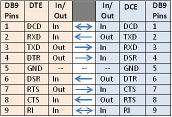
DTE - RS-232 to TTL
- The DTE (PC) has the male connector
Pin	SIG.	Signal Name		DTE (PC)
1	DCD	Data Carrier Detect	in
2	RXD	Receive Data		in
3	TXD	Transmit Data		out
4	DTR	Data Terminal Ready	out
5	GND	Signal Ground		-
6	DSR	Data Set Ready		in
7	RTS	Request to Send		out
8	CTS	Clear to Send		in
9	RI	Ring Indicator		in
- The DCE (peripheral) has the female.
H1 Connector
- Signal referenced to H1 connector
- GND
- RTS (out)
- VCC
- CTS (in)
- Tx (out)
- RX (in)
