Difference between revisions of "MHS-5200A DDS Signal Generator"
Jump to navigation
Jump to search
Blwikiadmin (talk | contribs) |
Blwikiadmin (talk | contribs) |
||
| Line 41: | Line 41: | ||
[[File:Pwr-Sply-Repl-P17223-720px.jpg]] | [[File:Pwr-Sply-Repl-P17223-720px.jpg]] | ||
| − | * Power | + | * Power switch close-up |
* DC switch looped back | * DC switch looped back | ||
Revision as of 12:26, 4 November 2020
Replace Wall-wart Power Supply
- Wall warts put AC on the ground.
- Fix it by replacing with an AC/DC linear supply
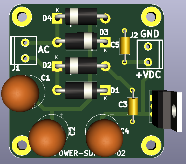
- Diodes backwards on silkscreen/image
Parts
- POWER XFMR 6.3Vct@1.2A 115V CHASSIS MOUNT w/LEADS/F-14X
- LF50ABV Voltage Regulator 5.0V 0.5A Positive
- Won;t work since unit draws 550 mA
- Using 7805
- 3x Aluminum Electrolytic Capacitors - Radial Leaded WCAP-ATG5 1200uF 16V 20% Radial
- 4x 1N5822-T Schottky Diodes & Rectifiers Vr/40V Io/3A T/R
- 2x 5mm terminal blocks
Installation
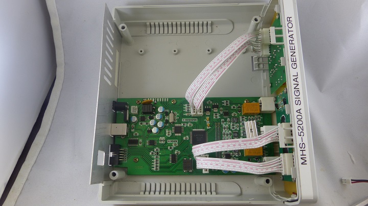
- Plenty of room inside
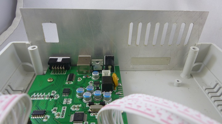
- Inside view of rear panel
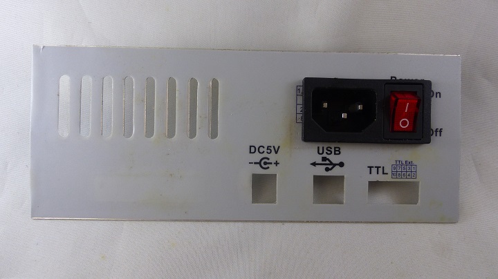
- Fit AC socket/switch where DC switch was located
- Cut with tin snips
- File for tight fit
- With AC socket/switch installed
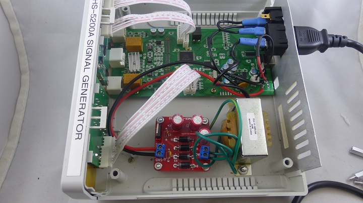
- With transformer/Power Supply board installed and wired
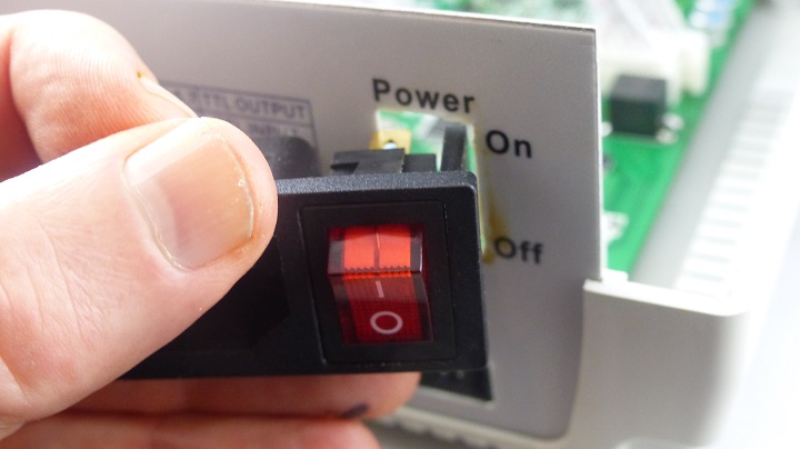
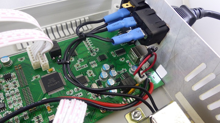
- Power switch close-up
- DC switch looped back
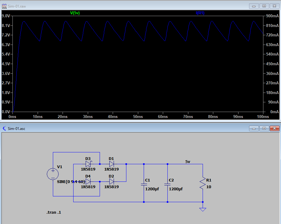
Simulation
6.8Vrms = 9.615V peak
Reviews / Fixes
