Difference between revisions of "Frequency Calibration via GPS"
Jump to navigation
Jump to search
Blwikiadmin (talk | contribs) |
Blwikiadmin (talk | contribs) |
||
| Line 44: | Line 44: | ||
** 5 parallel 74AC14 outputs with 249 ohm resistors on each output | ** 5 parallel 74AC14 outputs with 249 ohm resistors on each output | ||
* Able to drive long 50 ohm coax | * Able to drive long 50 ohm coax | ||
| − | * Square wave | + | * Square wave output |
| + | * Very fast edges | ||
== Videos == | == Videos == | ||
Revision as of 11:52, 1 December 2020
Inexpensive Frequency Standard with output synchronized to GPS satellites,
Contents
Features
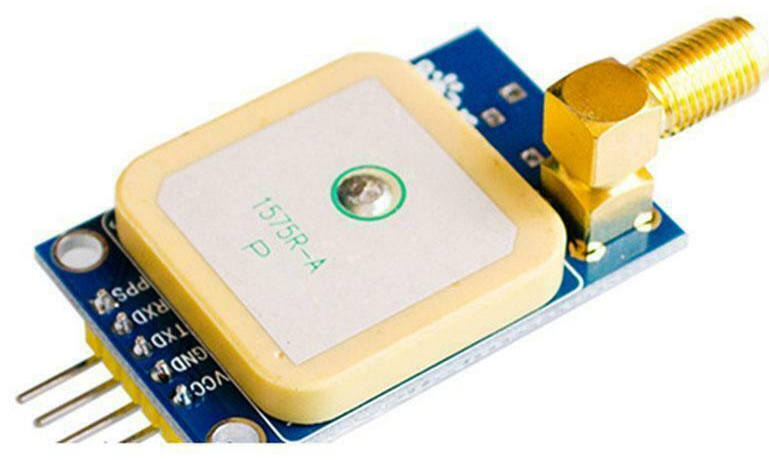
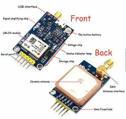
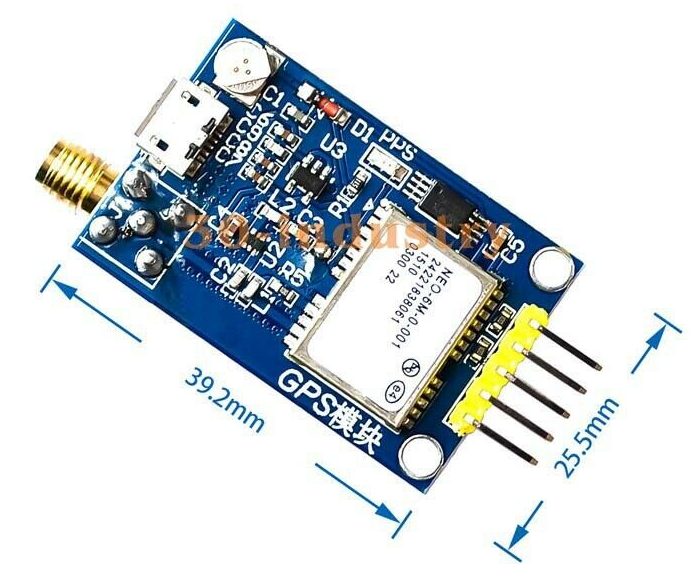
- U-Blox NEO-7M GPS Module
- Remote Amplified GPS Antenna
- SMA Male connector
- FTDI-49MM
- Used to program the GPS module
- Pulse Generator modified to provide 50 Ohms, 5V drive
- Mini-360 Switching Power Supply
- 5V out
- 7-23V in
Parts
GPS
- U-Blox NEO-7M GPS Module
- SMA Female connector
U-Center Programming Software
- U-Blox website
- Set to 8 MHz on GPS PPS pin when locked
- Other frequencies have some "jitter"
- Set to 2 Hz on GPS PPS pin when not locked
FTDI
50 Ohm Driver
- Used modified PulseGen card to drive 50 Ohms, 5V level output
- Remove oscillator circuit
- 5 parallel 74AC14 outputs with 249 ohm resistors on each output
- Able to drive long 50 ohm coax
- Square wave output
- Very fast edges
Videos
- GPSDO vs Rubidium Frequency Standard


