Difference between revisions of "OptoOut8-I2C"
Blwikiadmin (talk | contribs) |
Blwikiadmin (talk | contribs) |
||
| Line 214: | Line 214: | ||
Select Run Tests = "T" | Select Run Tests = "T" | ||
Observe test results | Observe test results | ||
| + | |||
| + | == Drivers == | ||
| + | |||
| + | * [https://github.com/land-boards/lb-Arduino-Code/tree/master/LBCards/OPTOOUT8I2C Arduino Example Code] | ||
| + | * [https://github.com/land-boards/lb-Arduino-Code/tree/master/libraries/LandBoards_MCP23008 LandBoards MCP23008 Arduino Library] | ||
| + | * [https://github.com/land-boards/lb-Python-Code/blob/master/MicroPython/ESP32/libraries/mcp23008/mcp23008.py MicroPython Library] | ||
| + | * [https://github.com/land-boards/RasPi/blob/master/Adafruit_I2C/Adafruit_MCP230xx.py Raspberry Adafruit Python library] - See Adafruit for latest version | ||
== Revision History == | == Revision History == | ||
Revision as of 22:28, 16 April 2021
Contents
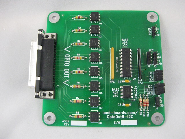
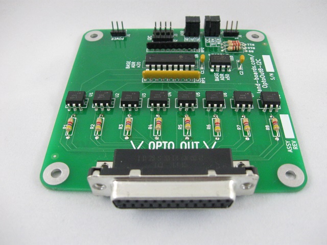
Eight Channel Optically Isolated Output Card with I2C bus
Features
- Eight optically-isolated output channels on card
- (8) 4N2x optoisolators
- I2C interface
- MCP23008 I2C Parallel I/O
- Two Wire interface
- 100/400 KHZ operation
- 25mA sink/source capability per I/O
- Jumper selectable terminators
- 3-bit address (Jumper selectable) - Up to 8 boards
- Single 4-pin host interface connector (Ground, Power, Clock, Data)
- 24LC024 Personality EEPROM
- 3.3V or 5V operation
- Compatible with Arduino, Raspberry Pi, BeagleBone Black
- DB-25 connector for rugged uses
- 95x95mm form factor
- (4) 6-32 mounting holes - one on each corner
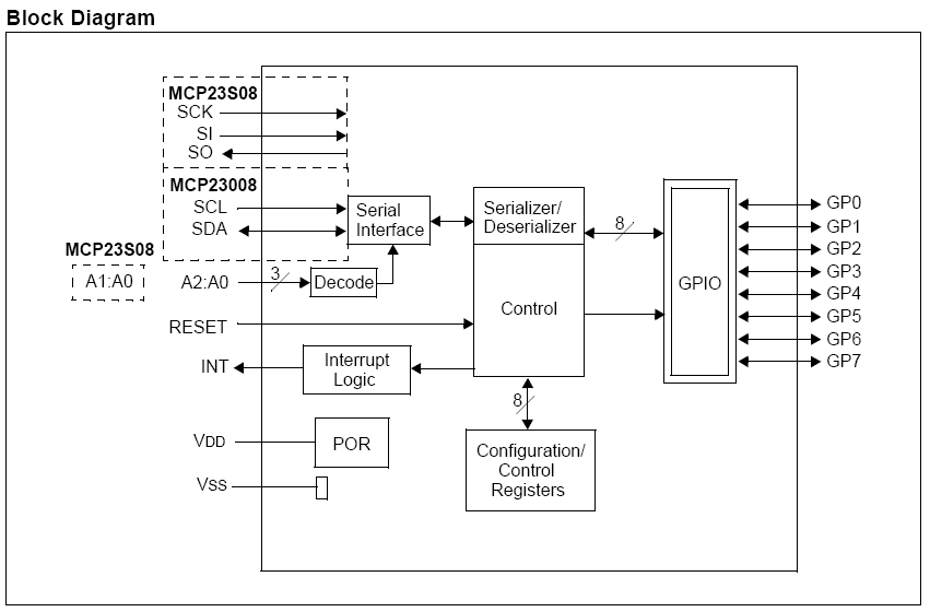
MCP23008 Block Diagram
Optocoupler Performance
- 4N25 Optocoupler
- DC Current Transfer Ratio
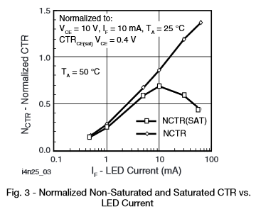
- Current Transfer ratio curve
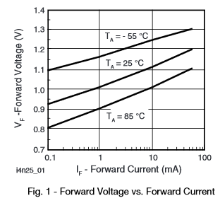
- LED Current vs voltage
- Output transistor capacitance
- Switching Time
Opto Characteristics
Current Transfer Ratio	10.00%	min
Vcc	5	V	3.3	V
Vf(Diode)	1.25	V	1.25	V
Res series LED	330	Ohms	330	Ohms
If (LED)	0.0113636364	A	0.0062121212	A
CTR	0.6	A/A	0.2	A/A
Current Trans CE	0.0068181818	A	0.0012424242	A
Res (load pullup)	4700	Ohms	4700	Ohms
Vce	0.2	V	0.2	V
V load side	5	V	5	V
Iload	0.0010212766		0.0010212766
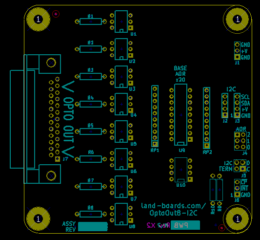
Connectors
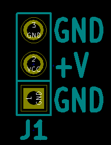
J1 - Power
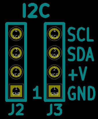
J2-J3 - I2C
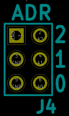
J4 - I2C Address Select Jumpers
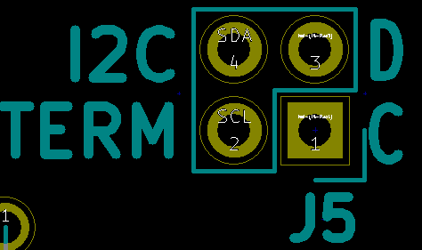
J5 - I2C Termination Jumpers
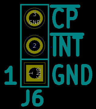
J6 - Card Present/Interrupt
- GND
- INT
- CP - Card present (pulled low)
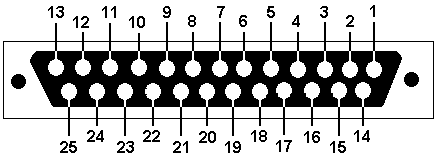
J7 - I/O connector
DB-25 Female
Pin Desc _ Pin Desc 1 S7 14 V7 2 G7 15 S6 3 V6 16 G6 4 S5 17 V5 5 G5 18 S4 6 V4 19 G4 7 S3 20 V3 8 G3 21 S2 9 V2 22 G2 10 S1 23 V1 11 G1 24 S0 12 V0 25 G0 13 N/C
Design Validation/First Article Test
- Test Code
Pass Count = 17977, Fail Count = 0
- Runs ODAS Card Test Software on Arduino Nano
- Loopback cables
- Cable connects to DB-25 and NANO-BKOUT pins
- USB running puTTY
- 9600 baud
- Menu driven
- Auto-detect card if test has been run before
Checking EEPROM for board type...Detected OptoIn8-I2C board
R=Read EEPROM, W=Write EEPROM, T=Test DIGIOs, L=Loop Test, B=Bounce LEDs
- Presents card type list for un-programmed EEPROMs
Checking EEPROM for board type...Company Mismatch
Select the board type
1 - DIGIO16-I2C board
2 - DIGIO-128 board
3 - OptoIn8-I2C board
4 - OptoOut8-I2C board
5 - DIGIO32-I2C board
6 - PROTO16-I2C board
7 - ODAS-PSOC5 board
8 - TBD board
9 - TBD board
Select board >
- Select board
Select board > 3
Writing EEPROM
Initializing eep buffer
len of buffer=96
reading block
Family=ODAS
Company=land.boards.com
- Test 'T'
- Fail (no cable)
OptoIn8-I2C failed HIGH on bit 1
Read back on  1
OptoIn8-I2C failed HIGH on bit 2
Read back on  2
OptoIn8-I2C failed HIGH on bit 4
Read back on  4
OptoIn8-I2C failed HIGH on bit 8
Read back on  8
OptoIn8-I2C failed HIGH on bit 16
Read back on  16
OptoIn8-I2C failed HIGH on bit 32
Read back on  32
OptoIn8-I2C failed HIGH on bit 64
Read back on  64
OptoIn8-I2C failed HIGH on bit 128
Read back on  128
Loopback Test PASS = 0, FAIL = 1
- Pass Checking EEPROM for board type...Detected OptoIn8-I2C board
R=Read EEPROM, W=Write EEPROM, T=Test DIGIOs, L=Loop Test, B=Bounce LEDs
Loopback Test PASS = 1, FAIL = 0
Production Tests
Test Station Set-up / Operation
- Uses ODAS Test Station V2
Test Station controls/read the Opto outputs via the DIGIO32 card in the Test Station Puts out 8 bits on OptoOut8-I2C card Reads the 8 bits on DIGIO32 card There are three lines per Channel that need to be connected: Ground (Gx), Power (Vx), Open Collector Output (Sx) If the LED is not being driven, the Open Collector output will be pulled up Wire Grounds to Digio32 channels 0-7 Wire Powers to Digio32 channels 8-15 Wire Signals to Digio32 channels 16-23 Resistors can be checked by setting the Power line high and checking the OC outputs OptoOut card is stimulated by writing to its I2C interface Verify that the Optos work
Test Steps
Attach Host Computer USB to the Arduino NANO on the Test Station Run puTTY on the Host Computer Program should prompt for the Card type or autodetect if the EEPROM on the card was already programmed Select Card Tests = "C" Select Run Tests = "T" Observe test results
Drivers
- Arduino Example Code
- LandBoards MCP23008 Arduino Library
- MicroPython Library
- Raspberry Adafruit Python library - See Adafruit for latest version
Revision History
Revision X4
- Move DB-25 mounting hole to center of pins
Revision X3
- Move DB-25 left
Revision X2
- Added I2C terminators and jumpers
- Added Write enable jumper
Layout Rev x2
Revision X1
- J5 pin 1 indicator needs to be moved
