Difference between revisions of "DTE"
Jump to navigation
Jump to search
Blwikiadmin (talk | contribs) |
Blwikiadmin (talk | contribs) |
||
| Line 32: | Line 32: | ||
== Test Procedure == | == Test Procedure == | ||
| + | |||
| + | [[File:DCE_DTE_Test_P554_720px.jpg]] | ||
* [[FTDI-49MM]] | * [[FTDI-49MM]] | ||
Revision as of 13:59, 18 July 2021
Contents
Features
- TTL to RS-232 converter
- DB-9 connector
- FTDI pinout (reversed directions to directly connect to FTDI Interface)
- 49x49mm card
- 4x 4-40 holes
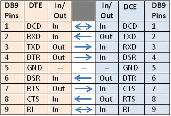
DTE - RS-232 to TTL
- The DTE (PC) has the male DB-9 connector
- The DCE (peripheral) has the DB-9 female.
H1 Connector
- Pins signal directions are reversed from an FTDI card
- Can be directly wired to FTDI connector
Pinout
- GND
- CTS (out)
- VCC (3.3V or 5V)
- TX (in)
- Rx (out)
- RTS (in)
- Pins 4 and 6 are backwards on Rev 1 card - corrected on Rev 2 card
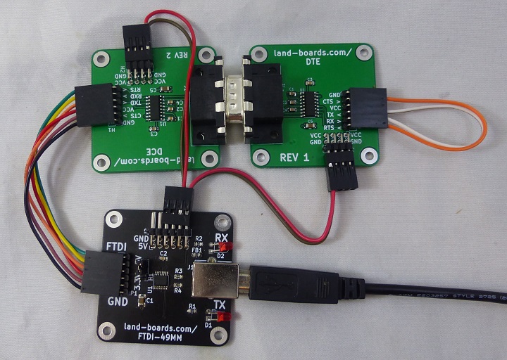
Test Procedure
- FTDI-49MM
- DCE/DTE Cards
- 9 pin connectors plugged together
- FTDI loopback cable
- TX/RX connected
- RTSCTS connected
- USB B cable to PC
- Run PuTTY
- 115,200 baud, RTS/CTS
- Type and it comes back
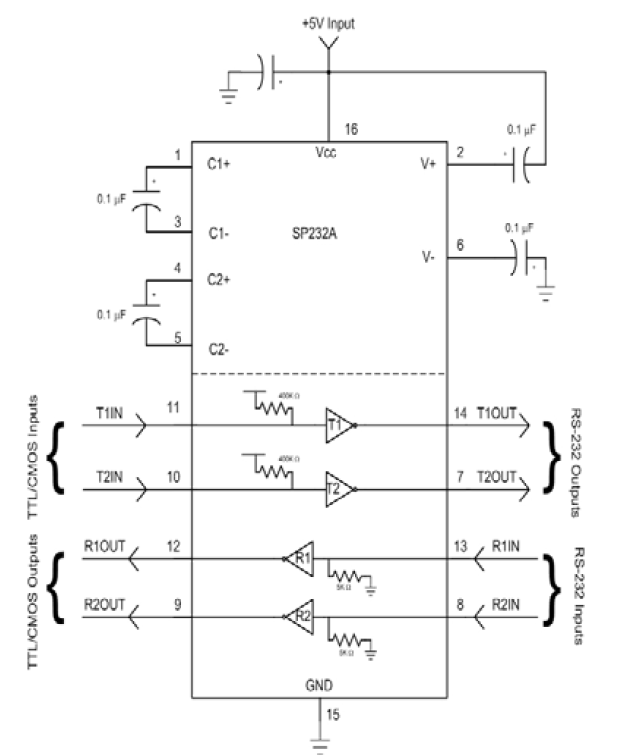
SP232A Application
- SP232ACN-L is 5V part
- ICL3232IBNZ is 3.3V or 5V part
DCE (reference)
- The DCE (Terminal) has the female connector


