Difference between revisions of "VFO-003"
Jump to navigation
Jump to search
Blwikiadmin (talk | contribs) |
Blwikiadmin (talk | contribs) |
||
| (30 intermediate revisions by the same user not shown) | |||
| Line 20: | Line 20: | ||
*** Run at 3.3V | *** Run at 3.3V | ||
** [https://www.ebay.com/sch/i.html?_from=R40&_trksid=p2334524.m570.l1312&_nkw=ec11+encoder&_sacat=0&LH_TitleDesc=0&_odkw=ssd1306+oled&_osacat=0 Rotary encoder with pushbutton] | ** [https://www.ebay.com/sch/i.html?_from=R40&_trksid=p2334524.m570.l1312&_nkw=ec11+encoder&_sacat=0&LH_TitleDesc=0&_odkw=ssd1306+oled&_osacat=0 Rotary encoder with pushbutton] | ||
| − | * Si5351A | + | * [https://www.skyworksinc.com/-/media/Skyworks/SL/documents/public/data-sheets/Si5351-B.pdf Si5351A Frequency Generator] |
** 3 Outputs | ** 3 Outputs | ||
** 3.3V, 50 Ohm outputs | ** 3.3V, 50 Ohm outputs | ||
** +12.6 dBm output | ** +12.6 dBm output | ||
** [https://www.mouser.com/ProductDetail/Fox-Abracon/FOX924B-27?qs=%2Fha2pyFaduhq6kU%252Bi5vLrAGjqnvi7J8gxS%252BDxofzmrc%3D 27 MHz TCXO crystal oscillator] | ** [https://www.mouser.com/ProductDetail/Fox-Abracon/FOX924B-27?qs=%2Fha2pyFaduhq6kU%252Bi5vLrAGjqnvi7J8gxS%252BDxofzmrc%3D 27 MHz TCXO crystal oscillator] | ||
| + | *** 2.5 PPM | ||
** I2C Interface | ** I2C Interface | ||
** [http://www.relmon.com/en/mobile/index.php/list/detail/347.html MS5351M Data Sheet] - Alternate part for Si5351A | ** [http://www.relmon.com/en/mobile/index.php/list/detail/347.html MS5351M Data Sheet] - Alternate part for Si5351A | ||
| Line 37: | Line 38: | ||
* Power | * Power | ||
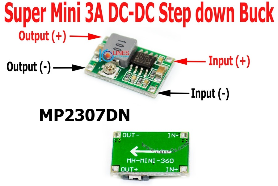
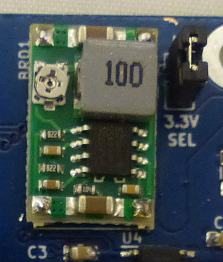
** [[Mini360_Buck_Converter|MINI-360 DC/DC Buck regulator]] | ** [[Mini360_Buck_Converter|MINI-360 DC/DC Buck regulator]] | ||
| − | ** 5- | + | ** 5-23 VDC |
** 30mA at 12VDC | ** 30mA at 12VDC | ||
** High efficiency | ** High efficiency | ||
| Line 168: | Line 169: | ||
[[file:VFO-003_J8.PNG]] | [[file:VFO-003_J8.PNG]] | ||
| − | === J12 - I2C === | + | === J9-J11 - SMA === |
| + | |||
| + | * SMA or BNC | ||
| + | |||
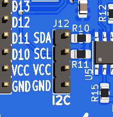
| + | === J12 - I2C (Rev 3) === | ||
[[file:VFO-003_J12.PNG]] | [[file:VFO-003_J12.PNG]] | ||
=== P1-P3 - Outputs (BNCs) === | === P1-P3 - Outputs (BNCs) === | ||
| + | |||
| + | * SMA or BNC | ||
| + | |||
| + | == Output Power - Power Calculation == | ||
| + | |||
| + | === RMS Voltage of square wave === | ||
| + | |||
| + | [[file:SquareWace-3.3V.PNG]] | ||
| + | |||
| + | * [https://www.redcrab-software.com/en/Calculator/Electrics/Rectangular-Voltage-RMS-Value Square Wave Calculator] | ||
| + | * 2.33V^2/100 = 0.0542W | ||
| + | * Power is split between Source and load resistors | ||
| + | * 0.02714W | ||
| + | |||
| + | === dBm Calculation === | ||
| + | |||
| + | * [https://www.rapidtables.com/convert/power/dbm-converter.html mW to dBm calculator] | ||
| + | |||
| + | [[file:SquareWave-3.3V_dBm.PNG]] | ||
| + | |||
| + | * Expect 14.3 dBm drive | ||
| + | * Measured 12.6 dBm with NanoVNA - Pretty close | ||
| + | * 3 dB attenuator to reduce for Level 7 mixers (like the ADE-1 mixer) | ||
== Measurements == | == Measurements == | ||
| Line 178: | Line 206: | ||
* [[NanoVNA]] | * [[NanoVNA]] | ||
* 10 Mhz signal from the VFO-003 | * 10 Mhz signal from the VFO-003 | ||
| − | * 1- | + | * 1-350 MHz |
[[file:tinysa_LOGMAG_S11_2021-10-12_12-29-43.png]] | [[file:tinysa_LOGMAG_S11_2021-10-12_12-29-43.png]] | ||
| Line 204: | Line 232: | ||
* [https://github.com/land-boards/lb-Arduino-Code/tree/master/LBCards/VFO-003 GitHub Repository] | * [https://github.com/land-boards/lb-Arduino-Code/tree/master/LBCards/VFO-003 GitHub Repository] | ||
| + | * [https://github.com/land-boards/lb-Arduino-Code/tree/VFO-003_MVP/LBCards/VFO-003 Minimal Viable Product build] - GitHub repo | ||
| + | |||
| + | ==== VFO Menu ==== | ||
| + | |||
| + | * Set Step Size | ||
| + | ** 1Hz, 10 Hz, 100 Hz, 1KHz, 10KHz, 100 KHz, 1 MHz, 10 MHz | ||
| + | * Set frequency | ||
| + | ** 10 KHz to 40 MHz in step size steps | ||
| + | * Select VFO | ||
| + | ** VFO0, VFO1, VFO2 | ||
| + | * VFO On/Off | ||
| + | ** On, Off | ||
| + | * Set Calibration Value | ||
| + | ** In step size steps (in 0.01 Hz steps) | ||
| + | * Save (power-on) defaults | ||
[[file:VFO-003_P1867-720pxV.jpg]] | [[file:VFO-003_P1867-720pxV.jpg]] | ||
| Line 209: | Line 252: | ||
=== Memory Usage === | === Memory Usage === | ||
| − | * [https://github.com/land-boards/lb-Arduino-Code/tree/VFO-003_MVP/LBCards/VFO-003 Minimal Viable Product Build] - GitHub repo | + | * [https://github.com/land-boards/lb-Arduino-Code/tree/VFO-003_MVP/LBCards/VFO-003 Minimal Viable Product Build] - GitHub repo branch |
* Arduino bootloader 2048 of Flash | * Arduino bootloader 2048 of Flash | ||
* Display code: 10260 of Flash and 1033 of SRAM using u8g2 | * Display code: 10260 of Flash and 1033 of SRAM using u8g2 | ||
| Line 279: | Line 322: | ||
* [https://github.com/land-boards/lb-Arduino-Code/tree/master/LBCards/U8X8Test Minimal U8X8Test code] | * [https://github.com/land-boards/lb-Arduino-Code/tree/master/LBCards/U8X8Test Minimal U8X8Test code] | ||
* [https://github.com/olikraus/u8g2/wiki/u8x8setupcpp u8x8 olikraus Library] | * [https://github.com/olikraus/u8g2/wiki/u8x8setupcpp u8x8 olikraus Library] | ||
| − | + | * [https://github.com/olikraus/u8g2/wiki/u8x8reference u8x8 Reference Guide] | |
<pre> | <pre> | ||
Sketch uses 6198 bytes (20%) of program storage space. Maximum is 30720 bytes. Global variables use 446 bytes (21%) of dynamic memory, leaving 1602 bytes for local variables. Maximum is 2048 bytes. | Sketch uses 6198 bytes (20%) of program storage space. Maximum is 30720 bytes. Global variables use 446 bytes (21%) of dynamic memory, leaving 1602 bytes for local variables. Maximum is 2048 bytes. | ||
| Line 309: | Line 352: | ||
} | } | ||
| + | </pre> | ||
| + | |||
| + | ==== I2C 16x2 LCD Minimal code ==== | ||
| + | |||
| + | * Hello World code | ||
| + | ** Much smaller code size than OLED code | ||
| + | |||
| + | <pre> | ||
| + | Sketch uses 3080 bytes (10%) of program storage space. Maximum is 30720 bytes. Global variables use 263 bytes (12%) of dynamic memory, leaving 1785 bytes for local variables. Maximum is 2048 bytes. | ||
</pre> | </pre> | ||
| Line 352: | Line 404: | ||
} | } | ||
</pre> | </pre> | ||
| + | |||
| + | ==== Rotary Encoder ==== | ||
| + | |||
| + | * [https://www.best-microcontroller-projects.com/rotary-encoder.html Best code] | ||
| + | ** Glitch free due to state machine | ||
| + | *** Test by going to top or bottom of the rotation and trying to go past end | ||
| + | ** Fast rotation rate | ||
| + | *** No delay loops for deglitching | ||
=== Feature Adds === | === Feature Adds === | ||
| Line 410: | Line 470: | ||
[[file:Rev3-_SMA_Smaller.PNG]] | [[file:Rev3-_SMA_Smaller.PNG]] | ||
| + | |||
| + | * Add ferrite bead and cap to power display board | ||
| + | * Add P2-P4 to J8 | ||
| + | ** Easier to tap into encoder lines (after filter) | ||
| + | * Add J13-J15 to break connections between drivers and BNC connectors | ||
| + | ** Cut jumper on rear side of card if needed | ||
== Assembly Sheet / Parts List == | == Assembly Sheet / Parts List == | ||
[[VFO-003 Assembly Sheet - Rev 1]] | [[VFO-003 Assembly Sheet - Rev 1]] | ||
Latest revision as of 18:14, 22 October 2021
Contents
- 1 Features
- 2 Connectors
- 2.1 J1 - OLED
- 2.2 J2 - Display Encoder/OLED (Display card)
- 2.3 J3 - Display Encoder/OLED (Main card)
- 2.4 J4 - FTDI
- 2.5 J5 - Arduino A0-A3/C10-D13
- 2.6 J6 - Disconnect for Mini-360 Power Supply
- 2.7 J7 - Output disconnects
- 2.8 J8 - Arduino P5-P9
- 2.9 J9-J11 - SMA
- 2.10 J12 - I2C (Rev 3)
- 2.11 P1-P3 - Outputs (BNCs)
- 3 Output Power - Power Calculation
- 4 Measurements
- 5 Schematic
- 6 Software
- 7 Mechanicals/Enclosure
- 8 Rev 1 Board Issues List
- 9 Rev 3 Design
- 10 Assembly Sheet / Parts List
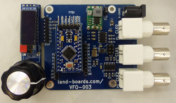
Features
Software controlled Variable Frequency Oscillator (VFO)
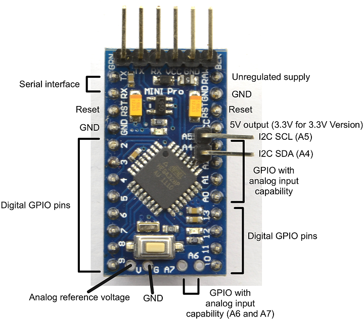
- Arduino Pro Mini Microprocessor
- 8-bit ATMEGA328 CPU
- 8 MHz
- 3.3V
- 30KB of Flash Memory (32KB - 2KB bootloader)
- 2KB of SRAM
- EEPROM
- Program Flash over FTDI connection
- Detachable Rotary Encoder/OLED card
- SSD1306 OLED Display
- I2C Interface
- 128x32 or 128x64
- Pins must be GND/VCC/SCL/SDA
- Run at 3.3V
- Rotary encoder with pushbutton
- SSD1306 OLED Display
- Si5351A Frequency Generator
- 3 Outputs
- 3.3V, 50 Ohm outputs
- +12.6 dBm output
- 27 MHz TCXO crystal oscillator
- 2.5 PPM
- I2C Interface
- MS5351M Data Sheet - Alternate part for Si5351A
- Menu options - Minimal Viable Product
- Select between 3 VFOs
- Adjust frequency
- Step sizes: 1Hz, 10 Hz, 100 Hz, 1 KHz, 10 KHz, 100 KHz, 1 MHz, 10 MHz steps (software controllable)
- Adjust frequency accuracy to 0.01 Hz precision
- Turn VFO Off/On (Off = 3.3V)
- Save default values which are loaded at power up
- Power
- MINI-360 DC/DC Buck regulator
- 5-23 VDC
- 30mA at 12VDC
- High efficiency
- Jumper to remove Power into card - protects 3.3V devices while adjusting the output voltage
- Fits in standard extruded enclosure
- Aluminum Project Box Enclosure DIY 100*76*35mm
Arduino Pro Mini
Power
- 5-24 VDC
- 30mA at 12VDC
- 55mA at 5V
- 35mA at 9V
- 28mA at 14V
- 33mA at 23V
TCXO
- TXCO requires very little frequency correction
- 27 MHz TCXO crystal oscillator
- Package / Case: 5 mm x 3.2 mm
- Frequency: 27 MHz
- Frequency Stability: 2.5 PPM
- Supply Voltage - Max: 3.3 V
- 25 MHz - Alternate would require software changes
Connectors
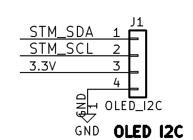
J1 - OLED
- Located on display/encoder board
- SDA
- SCL
- Vcc
- GND
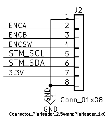
J2 - Display Encoder/OLED (Display card)
- Connect via cable to display/encoder board
- Encoder A
- Encoder B
- Encoder Switch
- SCL
- SDA
- Vcc
- GND
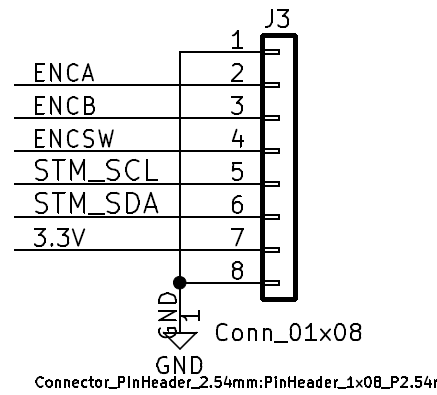
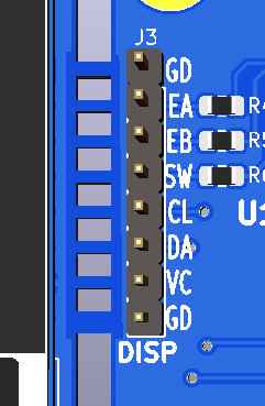
J3 - Display Encoder/OLED (Main card)
- Connect via cable to display/encoder board
- Encoder A
- Encoder B
- Encoder Switch
- SCL
- SDA
- Vcc
- GND
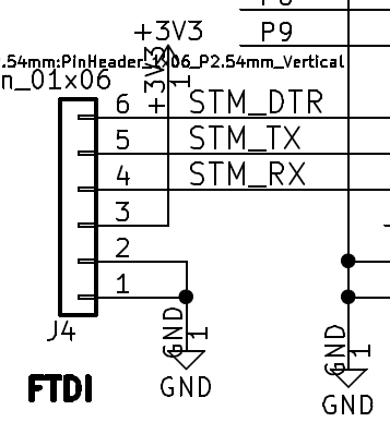
J4 - FTDI
- Can install 1x6 header on the Arduino Pro Mini and not install this
- GND
- GND
- Vcc
- RX
- Tx
- DTR
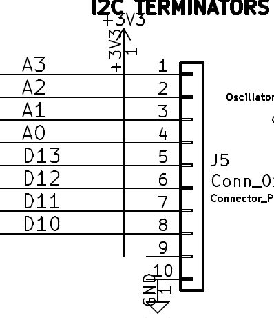
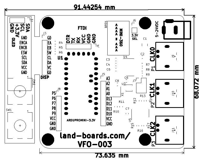
J5 - Arduino A0-A3/C10-D13
- A3
- A2
- A0
- D13
- D12
- D11
- D10
- Vcc (not connected on Rev 1 PCB)
- GND (not connected on Rev 1 PCB)
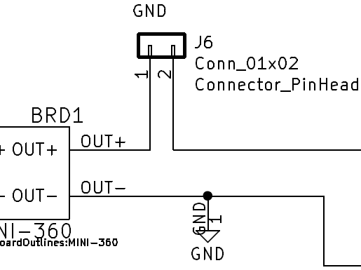
J6 - Disconnect for Mini-360 Power Supply
- The Mini360 Buck Converter comes adjusted for a very high output voltage
- Remove jumper to adjust the output voltage to 3.3V without powering the rest of the card
- Install to power the card from the power supply only after adjusting output
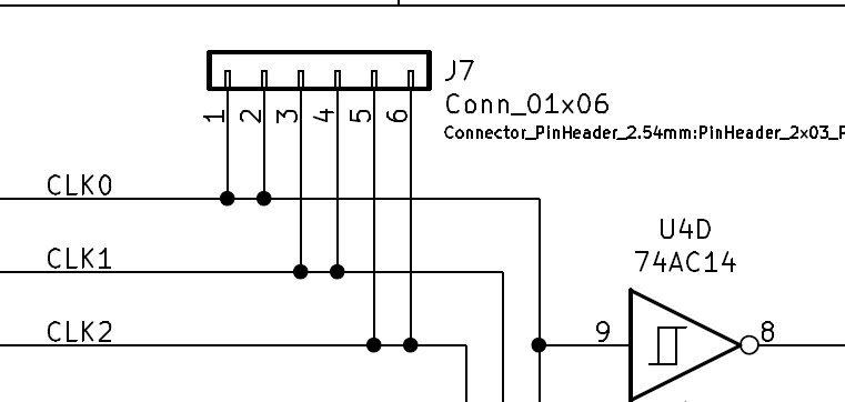
J7 - Output disconnects
- Cut rear side trace to disconnect
- Can be used to install external LP filters
- Limited use due to 74AC14 drivers
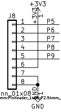
J8 - Arduino P5-P9
- P5
- P6
- P7
- P8
- P9
- Vcc
- GND
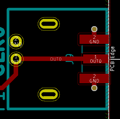
J9-J11 - SMA
- SMA or BNC
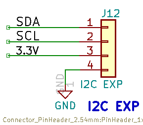
J12 - I2C (Rev 3)
P1-P3 - Outputs (BNCs)
- SMA or BNC
Output Power - Power Calculation
RMS Voltage of square wave
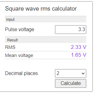
- Square Wave Calculator
- 2.33V^2/100 = 0.0542W
- Power is split between Source and load resistors
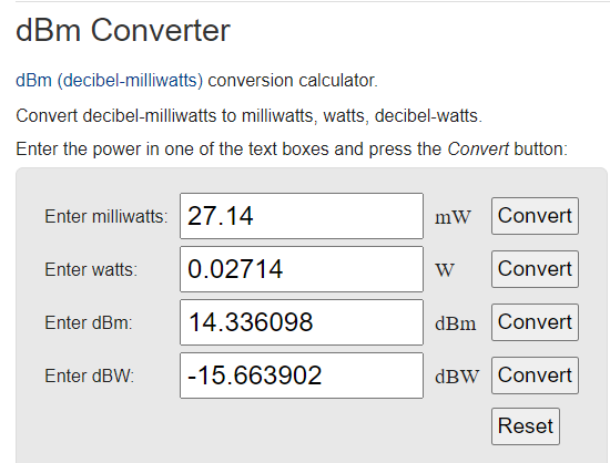
- 0.02714W
dBm Calculation
- Expect 14.3 dBm drive
- Measured 12.6 dBm with NanoVNA - Pretty close
- 3 dB attenuator to reduce for Level 7 mixers (like the ADE-1 mixer)
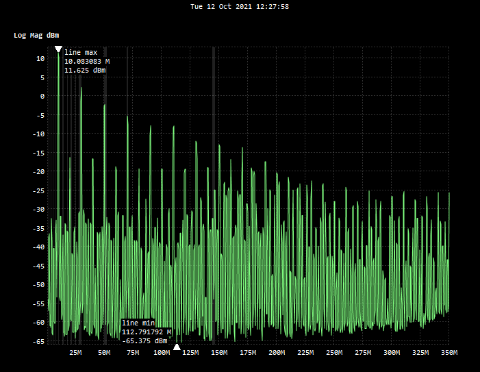
Measurements
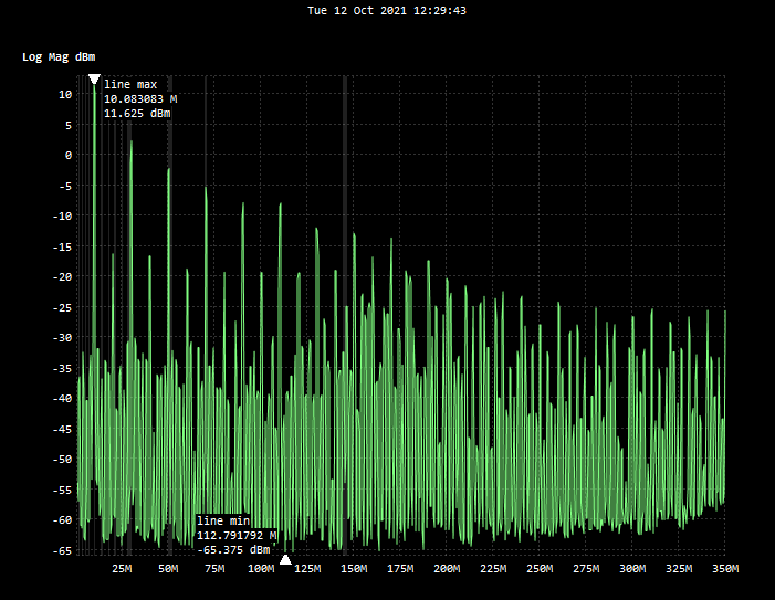
- NanoVNA
- 10 Mhz signal from the VFO-003
- 1-350 MHz
1-350 MHz scan
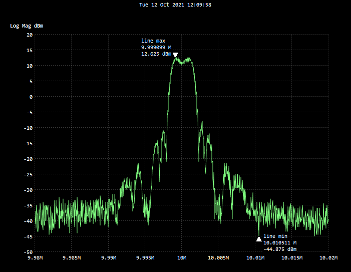
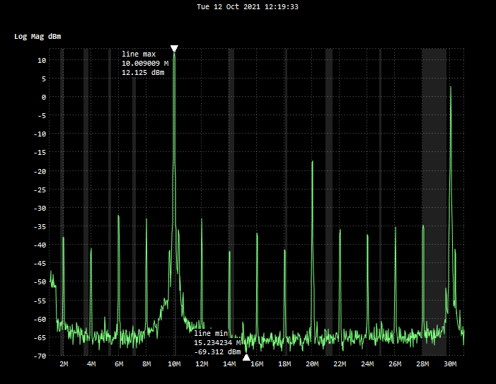
Harmonic content
- 10MHz fundamental = +12.25 dBm
- 20MHz harmonic = -16.75 dBm
- 30MHz harmonic = +2.4 dBm
- 50MHz harmonic = -2.1 dBm
Schematic
Software
- GitHub Repository
- Minimal Viable Product build - GitHub repo
VFO Menu
- Set Step Size
- 1Hz, 10 Hz, 100 Hz, 1KHz, 10KHz, 100 KHz, 1 MHz, 10 MHz
- Set frequency
- 10 KHz to 40 MHz in step size steps
- Select VFO
- VFO0, VFO1, VFO2
- VFO On/Off
- On, Off
- Set Calibration Value
- In step size steps (in 0.01 Hz steps)
- Save (power-on) defaults
Memory Usage
- Minimal Viable Product Build - GitHub repo branch
- Arduino bootloader 2048 of Flash
- Display code: 10260 of Flash and 1033 of SRAM using u8g2
- Alternate display code: 6198 of Flash and 446 of SRAM using u8x8
- Si5351 code: 12076 of Flash and 378 of SRAM
Total Memory usage with u8g2 Library
Sketch uses 25970 bytes (84%) of program storage space. Maximum is 30720 bytes. Global variables use 1503 bytes (73%) of dynamic memory, leaving 545 bytes for local variables. Maximum is 2048 bytes.
Total Memory usage with u8x8 Library
- ~4K less than the u2g2 library
Sketch uses 22064 bytes (71% of program storage space. Maximum is 30720 bytes. Global variables use 925 bytes (45%) of dynamic memory, leaving 1142 bytes for local variables. Maximum is 2048 bytes.
Minimal u8g2 code
Sketch uses 10260 bytes (33%) of program storage space. Maximum is 30720 bytes. Global variables use 1033 bytes (50%) of dynamic memory, leaving 1015 bytes for local variables. Maximum is 2048 bytes.
- Code
void setup(void)
{
  u8g2.begin();

}

void loop(void)
{
  printStringToOLED("VFO-003");
}

void printStringToOLED(char * charStr)
{
  u8g2.clearBuffer();
  u8g2_prepare();
  u8g2.drawStr( 0, 0, charStr);
  u8g2.sendBuffer();
}

// u8g2_prepare()
// Setup the screen font, etc
// List of fonts
// https://github.com/olikraus/u8g2/wiki/fntlist8#u8g2-fonts-capital-a-height-38
void u8g2_prepare(void)
{
  u8g2.setFont(u8g2_font_t0_11b_tf); // 8 Pixel tall font
  u8g2.setFontRefHeightExtendedText();
  u8g2.setDrawColor(1);
  u8g2.setFontPosTop();
  u8g2.setFontDirection(0);
}
Minimal u8x8 code
Sketch uses 6198 bytes (20%) of program storage space. Maximum is 30720 bytes. Global variables use 446 bytes (21%) of dynamic memory, leaving 1602 bytes for local variables. Maximum is 2048 bytes.
- Code
// https://github.com/olikraus/u8g2/wiki/u8x8reference#c-example

#include <Arduino.h>
#include <SPI.h>
#include <U8x8lib.h>

#define U8X8_HAVE_HW_I2C

U8X8_SSD1306_128X32_UNIVISION_HW_I2C u8x8(U8X8_PIN_NONE);

void setup() {
  // put your setup code here, to run once:
  u8x8.begin();
}

void loop() {
  // put your main code here, to run repeatedly:
  u8x8.setFont(u8x8_font_victoriabold8_r);
  u8x8.drawString(0,0,"Hello World!");
  delay(1000);

}
I2C 16x2 LCD Minimal code
- Hello World code
- Much smaller code size than OLED code
Sketch uses 3080 bytes (10%) of program storage space. Maximum is 30720 bytes. Global variables use 263 bytes (12%) of dynamic memory, leaving 1785 bytes for local variables. Maximum is 2048 bytes.
Minimal Si5351 code
Sketch uses 12072 bytes (39%) of program storage space. Maximum is 30720 bytes. Global variables use 378 bytes (18%) of dynamic memory, leaving 1670 bytes for local variables. Maximum is 2048 bytes.
#include <Arduino.h>
#include "si5351.h"

// Constructors
Si5351 si5351;
// End of constructor list

void setup(void)
{
  unsigned long VFO_0_Freq;
  unsigned long VFO_1_Freq;
  unsigned long VFO_2_Freq;
  bool i2c_found;
  VFO_0_Freq = 14000000;
  VFO_0_Freq = 14000000;
  VFO_0_Freq = 14000000;
  // Si8351 initialiation
  si5351.init(SI5351_CRYSTAL_LOAD_6PF, 27000000, 0);
  si5351.set_freq(VFO_0_Freq, SI5351_CLK0);
  si5351.set_freq(VFO_1_Freq, SI5351_CLK1);
  si5351.set_freq(VFO_2_Freq, SI5351_CLK2);
  si5351.update_status();
  si5351.set_correction(0, SI5351_PLL_INPUT_XO);
  si5351.drive_strength(SI5351_CLK0,SI5351_DRIVE_8MA);
  si5351.drive_strength(SI5351_CLK1,SI5351_DRIVE_8MA);
  si5351.drive_strength(SI5351_CLK2,SI5351_DRIVE_8MA);
}

void loop(void)
{
}
Rotary Encoder
- Best code
- Glitch free due to state machine
- Test by going to top or bottom of the rotation and trying to go past end
- Fast rotation rate
- No delay loops for deglitching
- Glitch free due to state machine
Feature Adds
- CAT control
- Pase control for the Si5351 - Generate IQ clocks 90 deg out of phase
Mechanicals/Enclosure
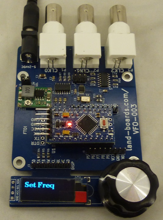
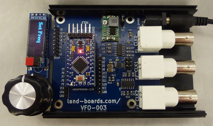
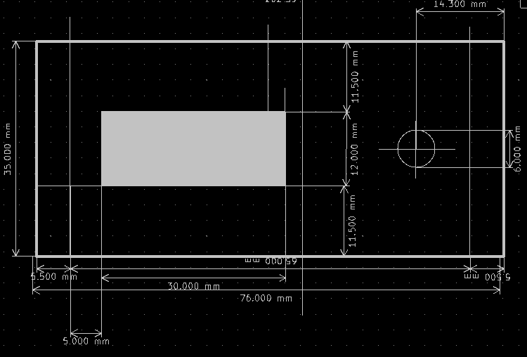
- Detachable Front Panel OLED with Rotary Encoder
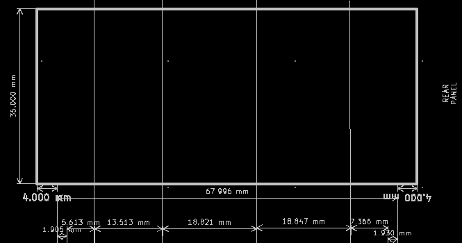
- Designed to fit into Aluminum Project Box Enclosure DIY 100*76*35mm - ebay search
Rev 1 Board Issues List
No major issues
- J5-9 and J5-10 are missing connections
- Add wires on reverse side of the PCB if needed
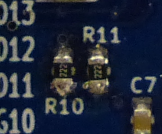
- Note orientation of I2C termination resistors
- Installed sideways by accident on first build
- Note orientation of Mini360
- Put on backwards on first build
- Always use a current limited power supply (I did, no damage)
- Always adjust Mini360 with 3.3V SEL jumper removed
- Solder in with short leads - space up a bit to allow rework
- Orientation is with inductor towards edge of card
Rev 3 Design
- Adds J12, I2C connector
- Use with I2C Peripheral like port expanders
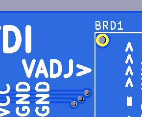
- Add silkscreen, "VADJ>" pointing to the adjustment pot on Mini360
- Add breakaways for Front Panel to make it easier to separate
- Switch to 0.1" pitch SMA edge launch connectors
- Add ferrite bead and cap to power display board
- Add P2-P4 to J8
- Easier to tap into encoder lines (after filter)
- Add J13-J15 to break connections between drivers and BNC connectors
- Cut jumper on rear side of card if needed
