Difference between revisions of "PulseGen"
Blwikiadmin (talk | contribs) |
Blwikiadmin (talk | contribs) (→Setup) |
||
| (43 intermediate revisions by the same user not shown) | |||
| Line 1: | Line 1: | ||
[[File:tindie-mediums.png|link=https://www.tindie.com/products/land_boards/coax-tester-fast-edge-pulse-gen-50-or-75-ohm/]] | [[File:tindie-mediums.png|link=https://www.tindie.com/products/land_boards/coax-tester-fast-edge-pulse-gen-50-or-75-ohm/]] | ||
| + | |||
| + | [[file:PulseGen_5242-720px.JPG]] | ||
== Fast Pulse Generator/Coax Tester == | == Fast Pulse Generator/Coax Tester == | ||
| Line 11: | Line 13: | ||
<video type="youtube">74fz9iwZ_sM</video> | <video type="youtube">74fz9iwZ_sM</video> | ||
| − | |||
| − | |||
== Features == | == Features == | ||
| − | * | + | * Very fast pulse edge (typical 2 nS rise time) and symmetric high/low drive. |
* 5mm Terminal Block for power allows for batteries, etc to be easily connected without soldering | * 5mm Terminal Block for power allows for batteries, etc to be easily connected without soldering | ||
| − | * | + | ** Power Supply from 2V to 6V range so battery operation is possible eliminating need for power supply, etc |
* 50 or 75 Ohm (other values could be made, send us your specs and we can add them) | * 50 or 75 Ohm (other values could be made, send us your specs and we can add them) | ||
* BNC connectors on both ends | * BNC connectors on both ends | ||
| Line 37: | Line 37: | ||
[[file:PulseGenInCaseP1030838.JPG]] | [[file:PulseGenInCaseP1030838.JPG]] | ||
| − | 3D Printed case in picture not included - [https://github.com/land-boards/lb-Printed-Parts/tree/master/Board%20Enclosures%20and%20Frames/PulseGen- | + | 3D Printed case in picture not included - [https://github.com/land-boards/lb-Printed-Parts/tree/master/Board%20Enclosures%20and%20Frames/PulseGen-Box printer files are here]. |
* Case | * Case | ||
| Line 62: | Line 62: | ||
== Factory Acceptance Test (FAT) Procedure == | == Factory Acceptance Test (FAT) Procedure == | ||
| − | + | [[File:PulseGen_TestStation_P18373-720px.jpg]] | |
| − | === | + | === Setup === |
| − | * | + | * [[QTPy49]] or [[QTPy49-01]] Processor card |
| − | * | + | * [[QT_Py_(RP2040_based)]] |
| + | ** A0 - Analog Input - samples | ||
| + | * [[MyMenu]] | ||
| + | * Power card options | ||
| + | ** Connect USB-C to the [[QT_Py_(RP2040_based)]] or | ||
| + | ** Power from 9-12V to DC jack | ||
| + | * Cables | ||
| + | ** USB-C (power option) | ||
| + | ** Power cable to UUT | ||
| + | ** Analog in (BNC) to A0 on [[QTPy49]] | ||
* Terminator - dependent on build option | * Terminator - dependent on build option | ||
** 50 Ohms | ** 50 Ohms | ||
| Line 73: | Line 82: | ||
* Unit Under Test (UUT) | * Unit Under Test (UUT) | ||
| − | ==== | + | === Test Software === |
| + | |||
| + | * [https://github.com/land-boards/QT-Py/blob/main/CircuitPython/lbcards/PulseGen/PulseGen_DRIVE50_Test.py PulseGen_DRIVE50_Test.py] - Tests PulseGen and DRIVE50 cards | ||
| + | ** Stored as code.py on [[QT_Py_(RP2040_based)]] to auto-run | ||
| + | ** Auto-detects card type | ||
| + | |||
| + | === Test Steps === | ||
| + | |||
| + | * Connect Power from STE to UUT | ||
| + | ** Connector is 3 pin Dupont housing with 2 male pins (center pin open) | ||
| + | ** Minus (black) goes to the left (- marked on UUT) | ||
| + | ** Plus goes to the right (+ marked on UUT - towards C2 capacitor) | ||
| + | * Connect BNC cable from STE to SCOPE connector on UUT | ||
| + | * Add terminator | ||
| + | * Results display on OLED and LEDs on [[MyMenu]] card | ||
| − | + | <pre> | |
| − | + | PulseGen Tester V1.0 | |
| − | + | Measure Freq | |
| − | + | Freq in range OR Freq out of range | |
| − | * | + | Looking for low |
| − | + | Got Low | |
| − | + | Got HIGH term | |
| − | + | </pre> | |
| − | + | ||
| + | * Remove terminator | ||
| + | |||
| + | <pre> | ||
| + | Got HIGH un-term | ||
| + | Detected all values | ||
| + | </pre> | ||
=== Test Steps === | === Test Steps === | ||
* Connect Power from STE to UUT | * Connect Power from STE to UUT | ||
| − | * | + | ** Connector is 3 pin Dupont housing with 2 male pins (center pin open) |
| − | * | + | ** Minus (black) goes to the left (- marked on UUT) |
| + | ** Plus goes to the right (+ marked on UUT - towards C2 capacitor) | ||
| + | * Connect BNC cable from STE to SCOPE connector on UUT | ||
* Add terminator | * Add terminator | ||
| − | * | + | * Results display on OLED and LEDs on [[MyMenu]] card |
| + | |||
| + | <pre> | ||
| + | PulseGen Tester V1.0 | ||
| + | Measure Freq | ||
| + | Freq in range OR Freq out of range | ||
| + | Looking for low | ||
| + | Got Low | ||
| + | Got HIGH term | ||
| + | </pre> | ||
| + | |||
| + | * Remove terminator | ||
| + | |||
| + | <pre> | ||
| + | Got HIGH un-term | ||
| + | Detected all values | ||
| + | </pre> | ||
| + | |||
| + | == Modifications to Use as a 50 Ohm Driver == | ||
| + | |||
| + | * [[DRIVE50]] card replaces this | ||
| + | * The card can be used as an embedded 50 Ohm driver | ||
| + | ** The R/C pair for the oscillator is omitted | ||
| + | ** 2nd BNC is omitted | ||
| + | * Card can be ordered on Tindie as 50 Ohm driver card | ||
| + | * [[GPS_Frequency_Standard#50_Ohm_Driver|Detailed instructions for 50 Ohm driver build]] | ||
| + | * Test using [https://github.com/land-boards/QT-Py/blob/main/CircuitPython/lbcards/GPS/Test50-01.py Test50-01.py] | ||
| + | |||
| + | == Mechanicals == | ||
| + | |||
| + | [[file:PulseGen_RevX6_Mechs.png]] | ||
== Assembly Sheet == | == Assembly Sheet == | ||
* [[PulseGen Assembly Sheet]] | * [[PulseGen Assembly Sheet]] | ||
Latest revision as of 11:23, 20 August 2022
Contents
Fast Pulse Generator/Coax Tester
- Uses of the Fast Pulse Generator
- Start at 15:12
ht
Features
- Very fast pulse edge (typical 2 nS rise time) and symmetric high/low drive.
- 5mm Terminal Block for power allows for batteries, etc to be easily connected without soldering
- Power Supply from 2V to 6V range so battery operation is possible eliminating need for power supply, etc
- 50 or 75 Ohm (other values could be made, send us your specs and we can add them)
- BNC connectors on both ends
- Connectors are a stuffing option with either BNC or SMA connectors (SMA is a special order so contact us)
- Four mounting holes - 4-40 holes
- Rounded corners fit more easily into plastic enclosures with inside radius at the corners
- Nuts and washers for BNC mounting included
- Small size (1.8" x 1.3)
What is it?
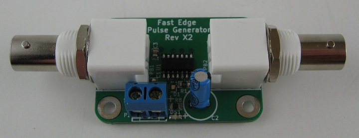
Fast Edge Pulse Generator for use as a Time Domain Reflectometer (TDR). Used to measure cable length and test continuity/termination of 50 or 75 Ohm coax cables.
Requires a fast oscilloscope for precision measurement. To use it, plug one BNC using male-to-male adapter into a scope and attach a cable to the other BNC connector. Allows measurement of the cable and determination if there is a cable defect (open/short, termination, Etc.).
3D Printed Case
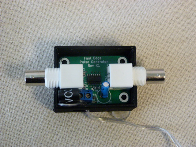
3D Printed case in picture not included - printer files are here.
- Case
- Lid
Why did you make it?
The video, by W2AEW, inspired me to want to make a Pulse Generator for use with an oscilloscope as a Time Domain Reflectometer (TDR). There were some DIY boards available but none that are as good as this design.
What makes it special?
Within a month of first building this board, I had a bad piece of RG-8X coax and it was difficult to diagnose the problem. I used an ohmmeter to verify that the coax was good from a DC perspective and it looked fine while I was testing with the meter. It was connected end to end and there were no opens or shorts that I could see with the meter.
However, I knew the cable was bad because I swapped it out for another cable and the other cable worked just fine. When I went to use the broken cable, I could jiggle the cable and make it work and then it would flake out but it was far from consistent. Intermittent problems are the worst sort of problems, aren't they? As they say - Murphy's Law is a universal constant.
I decided to hook the questionable coax up to this Pulse Generator board and the results were impressive to say the least. When I flexed the cable the waveform went from a nice stepped waveform to nearly flat on my oscilloscope (a little bump which went down quickly). That told me that the problem was on the near end of the cable and that it was a short between the center conductor and the shield. In the end the problem was a short at the PL-259 connector which (once found) was easily repaired.
Factory Acceptance Test (FAT) Procedure
Setup
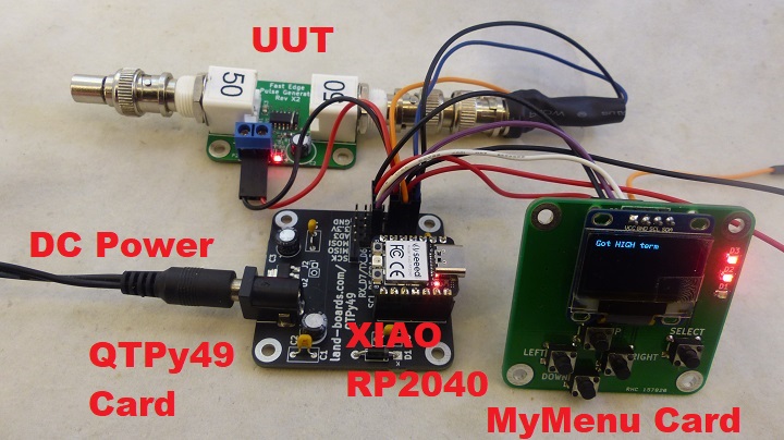
- QTPy49 or QTPy49-01 Processor card
- QT_Py_(RP2040_based)
- A0 - Analog Input - samples
- MyMenu
- Power card options
- Connect USB-C to the QT_Py_(RP2040_based) or
- Power from 9-12V to DC jack
- Cables
- USB-C (power option)
- Power cable to UUT
- Analog in (BNC) to A0 on QTPy49
- Terminator - dependent on build option
- 50 Ohms
- 75 Ohms
- Unit Under Test (UUT)
Test Software
- PulseGen_DRIVE50_Test.py - Tests PulseGen and DRIVE50 cards
- Stored as code.py on QT_Py_(RP2040_based) to auto-run
- Auto-detects card type
Test Steps
- Connect Power from STE to UUT
- Connector is 3 pin Dupont housing with 2 male pins (center pin open)
- Minus (black) goes to the left (- marked on UUT)
- Plus goes to the right (+ marked on UUT - towards C2 capacitor)
- Connect BNC cable from STE to SCOPE connector on UUT
- Add terminator
- Results display on OLED and LEDs on MyMenu card
PulseGen Tester V1.0
Measure Freq
Freq in range OR Freq out of range
Looking for low
Got Low
Got HIGH term
- Remove terminator
Got HIGH un-term
Detected all values
Modifications to Use as a 50 Ohm Driver
- DRIVE50 card replaces this
- The card can be used as an embedded 50 Ohm driver
- The R/C pair for the oscillator is omitted
- 2nd BNC is omitted
- Card can be ordered on Tindie as 50 Ohm driver card
- Detailed instructions for 50 Ohm driver build
- Test using Test50-01.py


