Difference between revisions of "QMTECH Cyclone 10CL006 FPGA Card"
Jump to navigation
Jump to search
Blwikiadmin (talk | contribs) (→LEDs) |
Blwikiadmin (talk | contribs) (→U8) |
||
| (24 intermediate revisions by the same user not shown) | |||
| Line 1: | Line 1: | ||
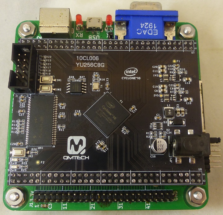
| + | [[FILE:CYCLONE10_P18103_720PX.jpg]] | ||
| + | |||
== Specification == | == Specification == | ||
| − | * | + | * Mounts to [[RETRO-EP4CE15]] |
| − | * On-Board FPGA external crystal frequency: 50MHz | + | * FPGA: 10CL006YU256C8G |
| − | * | + | ** On-Board FPGA external crystal frequency: 50MHz |
| − | * | + | ** Block RAM resource - 30 of M9K blocks |
| + | ** 6K LEs | ||
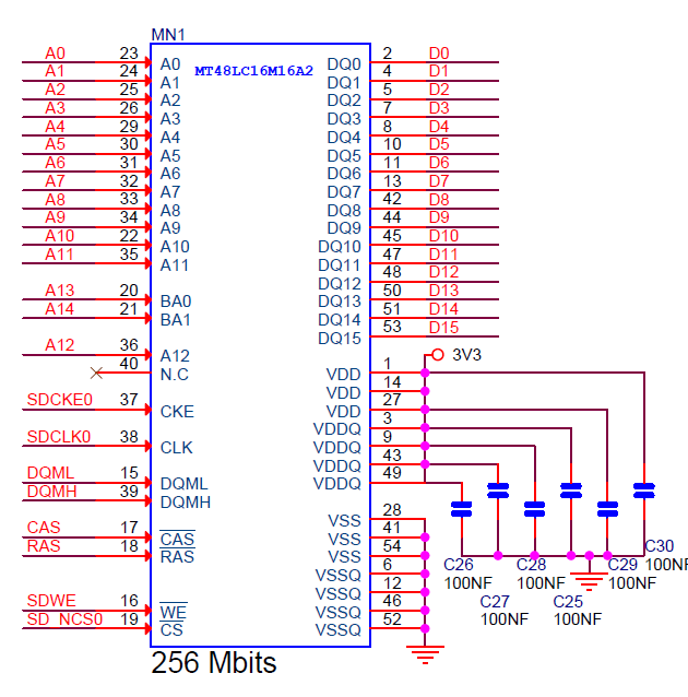
* On-Board 32MB Micron SDRAM,MT48LC16M16A2-75 | * On-Board 32MB Micron SDRAM,MT48LC16M16A2-75 | ||
* On-Board 3.3V power supply for FPGA by using MP2359 wide input range DC/DC | * On-Board 3.3V power supply for FPGA by using MP2359 wide input range DC/DC | ||
| − | * | + | * Two 64p, 2.54mm pitch headers for extending user IOs |
| − | * | + | * 3 user switches |
| − | * | + | * 2 user LEDs |
| − | * | + | * JTAG interface, by using 10p, 2.54mm pitch male header |
| − | * | + | * PCB size is: 6.7cm x 8.4cm |
* Default power source for board is: 1A@5V DC, the DC header type: DC-050, 5.5mmx2.1mm | * Default power source for board is: 1A@5V DC, the DC header type: DC-050, 5.5mmx2.1mm | ||
| + | * [https://github.com/ChinaQMTECH/QM_Cyclone10_10CL006 Cyclone10 10CL006 GitHub] | ||
* [https://www.aliexpress.com/item/1000006634063.html?pdp_ext_f=%7B%22sku_id%22:%2212000021636714875%22,%22ship_from%22:%22%22%7D&gps-id=pcStoreJustForYou&scm=1007.23125.137358.0&scm_id=1007.23125.137358.0&scm-url=1007.23125.137358.0&pvid=5044a8e4-9840-4ce7-8407-1416b7f510a9&spm=a2g0o.store_pc_home.smartJustForYou_482569341.1 AliExpress listing] | * [https://www.aliexpress.com/item/1000006634063.html?pdp_ext_f=%7B%22sku_id%22:%2212000021636714875%22,%22ship_from%22:%22%22%7D&gps-id=pcStoreJustForYou&scm=1007.23125.137358.0&scm_id=1007.23125.137358.0&scm-url=1007.23125.137358.0&pvid=5044a8e4-9840-4ce7-8407-1416b7f510a9&spm=a2g0o.store_pc_home.smartJustForYou_482569341.1 AliExpress listing] | ||
== Resources == | == Resources == | ||
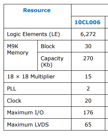
| − | * | + | * 10CL006 is comparable to Cyclone IV EP4CE6 FPGA |
[[file:Cyclone_10_Resources.PNG]] | [[file:Cyclone_10_Resources.PNG]] | ||
| Line 24: | Line 28: | ||
* Power LED - D4 (On when 5V is applied) | * Power LED - D4 (On when 5V is applied) | ||
| − | |||
| − | |||
| − | |||
* nCONFIG - SW3 - FPGA PIN_H5 | * nCONFIG - SW3 - FPGA PIN_H5 | ||
* JP5 - 5V | * JP5 - 5V | ||
| + | |||
| + | {| class="wikitable" | ||
| + | ! To | ||
| + | ! Direction | ||
| + | ! Location | ||
| + | ! I/O Standard | ||
| + | ! Pull-Up | ||
| + | |- | ||
| + | | i_clk | ||
| + | | Input | ||
| + | | PIN_E1 | ||
| + | | 3.3-V LVTTL | ||
| + | | | ||
| + | |- | ||
| + | | i_SW1 | ||
| + | | Input | ||
| + | | PIN_F3 | ||
| + | | 3.3-V LVTTL | ||
| + | | on | ||
| + | |- | ||
| + | | i_n_reset | ||
| + | | Input | ||
| + | | PIN_J6 | ||
| + | | 3.3-V LVTTL | ||
| + | | on | ||
| + | |- | ||
| + | | USR_LED | ||
| + | | Output | ||
| + | | PIN_L9 | ||
| + | | 3.3-V LVTTL | ||
| + | | | ||
| + | |- | ||
| + | |} | ||
== Connectors == | == Connectors == | ||
| Line 47: | Line 81: | ||
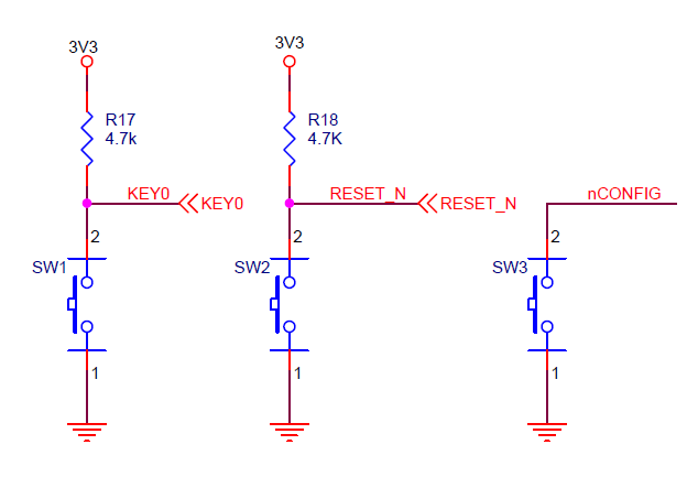
=== Pushbuttons === | === Pushbuttons === | ||
| + | |||
| + | * KEY0 - SW1 - FPGA Pin_F3 | ||
| + | * RESET_N- SW2 - FPGA PIN_J6 | ||
| + | * nCONFIG - SW3 - FPGA PIN_H5 | ||
[[file:Pushbuttons_C10.PNG]] | [[file:Pushbuttons_C10.PNG]] | ||
| Line 59: | Line 97: | ||
=== U8 === | === U8 === | ||
| + | |||
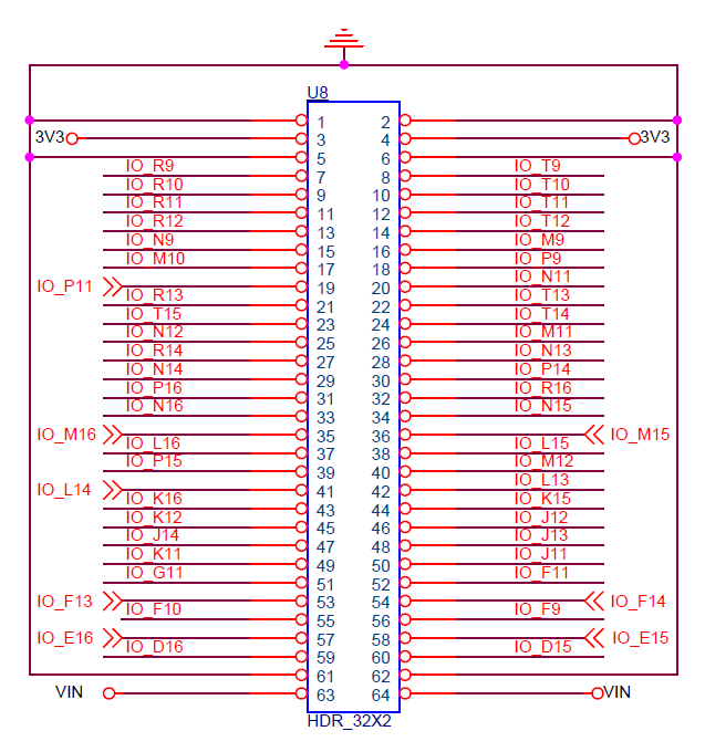
| + | * Cannot place output or bidirectional pin J8IO[35] in input pin location M16 | ||
| + | * Cannot place output or bidirectional pin J8IO[36] in input pin location M15 | ||
| + | * Cannot place output or bidirectional pin J8IO[57] in input pin location E16 | ||
| + | * Cannot place output or bidirectional pin J8IO[58] in input pin location E15 | ||
| + | |||
[[file:U8_C10.PNG]] | [[file:U8_C10.PNG]] | ||
| + | |||
| + | == Programmer - Create jic file == | ||
| + | |||
| + | * .jic file | ||
| + | * Device EPCQ64 | ||
| + | * Active Serial | ||
| + | * Programming File Type: *.jic | ||
| + | * Advanced = Check both Disables... | ||
| + | * Select Flash Loader | ||
| + | |||
| + | [[file:Cyclone10_Gen_Programmer_File.png]] | ||
| + | |||
| + | * Adv Options | ||
| + | ** Click first 2 boxes | ||
| + | |||
| + | [[file:Cyclone10_Adv_Opts_Programmer.png]] | ||
| + | |||
| + | * Programmer | ||
| + | |||
| + | [[file:Cyclone10_Programmer.png]] | ||
== Pin List == | == Pin List == | ||
| + | |||
| + | * Used on [[RETRO-EP4CE15]] card | ||
| + | |||
| + | {| class="wikitable" | ||
| + | ! To | ||
| + | ! Direction | ||
| + | ! Location | ||
| + | ! I/O Standard | ||
| + | ! Pull-Up | ||
| + | |- | ||
| + | | cts1 | ||
| + | | Input | ||
| + | | PIN_D11 | ||
| + | | 3.3-V LVTTL | ||
| + | | | ||
| + | |- | ||
| + | | hSync | ||
| + | | Output | ||
| + | | PIN_D14 | ||
| + | | 3.3-V LVTTL | ||
| + | | | ||
| + | |- | ||
| + | | i_clk | ||
| + | | Input | ||
| + | | PIN_E1 | ||
| + | | 3.3-V LVTTL | ||
| + | | | ||
| + | |- | ||
| + | | i_key1 | ||
| + | | Input | ||
| + | | PIN_F3 | ||
| + | | 3.3-V LVTTL | ||
| + | | on | ||
| + | |- | ||
| + | | i_n_reset | ||
| + | | Input | ||
| + | | PIN_J6 | ||
| + | | 3.3-V LVTTL | ||
| + | | on | ||
| + | |- | ||
| + | | n_sdRamCas | ||
| + | | Output | ||
| + | | PIN_M7 | ||
| + | | 3.3-V LVTTL | ||
| + | | | ||
| + | |- | ||
| + | | n_sdRamCe | ||
| + | | Output | ||
| + | | PIN_P8 | ||
| + | | 3.3-V LVTTL | ||
| + | | | ||
| + | |- | ||
| + | | n_sdRamRas | ||
| + | | Output | ||
| + | | PIN_M8 | ||
| + | | 3.3-V LVTTL | ||
| + | | | ||
| + | |- | ||
| + | | n_sdRamWe | ||
| + | | Output | ||
| + | | PIN_P6 | ||
| + | | 3.3-V LVTTL | ||
| + | | | ||
| + | |- | ||
| + | | n_sRamCS | ||
| + | | Output | ||
| + | | PIN_E5 | ||
| + | | 3.3-V LVTTL | ||
| + | | | ||
| + | |- | ||
| + | | n_sRamOE | ||
| + | | Output | ||
| + | | PIN_A3 | ||
| + | | 3.3-V LVTTL | ||
| + | | | ||
| + | |- | ||
| + | | n_sRamWE | ||
| + | | Output | ||
| + | | PIN_B7 | ||
| + | | 3.3-V LVTTL | ||
| + | | | ||
| + | |- | ||
| + | | o_UsrLed | ||
| + | | Output | ||
| + | | PIN_L9 | ||
| + | | 3.3-V LVTTL | ||
| + | | | ||
| + | |- | ||
| + | | ps2Clk | ||
| + | | Bidir | ||
| + | | PIN_G1 | ||
| + | | 3.3-V LVTTL | ||
| + | | on | ||
| + | |- | ||
| + | | ps2Data | ||
| + | | Bidir | ||
| + | | PIN_G2 | ||
| + | | 3.3-V LVTTL | ||
| + | | on | ||
| + | |- | ||
| + | | rts1 | ||
| + | | Output | ||
| + | | PIN_B10 | ||
| + | | 3.3-V LVTTL | ||
| + | | | ||
| + | |- | ||
| + | | rxd1 | ||
| + | | Input | ||
| + | | PIN_D12 | ||
| + | | 3.3-V LVTTL | ||
| + | | | ||
| + | |- | ||
| + | | sdCS | ||
| + | | Output | ||
| + | | PIN_B16 | ||
| + | | 3.3-V LVTTL | ||
| + | | | ||
| + | |- | ||
| + | | sdMISO | ||
| + | | Input | ||
| + | | PIN_C15 | ||
| + | | 3.3-V LVTTL | ||
| + | | on | ||
| + | |- | ||
| + | | sdMOSI | ||
| + | | Output | ||
| + | | PIN_A15 | ||
| + | | 3.3-V LVTTL | ||
| + | | | ||
| + | |- | ||
| + | | sdRamAddr[14] | ||
| + | | Output | ||
| + | | PIN_L8 | ||
| + | | 3.3-V LVTTL | ||
| + | | | ||
| + | |- | ||
| + | | sdRamAddr[13] | ||
| + | | Output | ||
| + | | PIN_N8 | ||
| + | | 3.3-V LVTTL | ||
| + | | | ||
| + | |- | ||
| + | | sdRamAddr[12] | ||
| + | | Output | ||
| + | | PIN_T2 | ||
| + | | 3.3-V LVTTL | ||
| + | | | ||
| + | |- | ||
| + | | sdRamAddr[11] | ||
| + | | Output | ||
| + | | PIN_R3 | ||
| + | | 3.3-V LVTTL | ||
| + | | | ||
| + | |- | ||
| + | | sdRamAddr[10] | ||
| + | | Output | ||
| + | | PIN_T6 | ||
| + | | 3.3-V LVTTL | ||
| + | | | ||
| + | |- | ||
| + | | sdRamAddr[9] | ||
| + | | Output | ||
| + | | PIN_T3 | ||
| + | | 3.3-V LVTTL | ||
| + | | | ||
| + | |- | ||
| + | | sdRamAddr[8] | ||
| + | | Output | ||
| + | | PIN_R4 | ||
| + | | 3.3-V LVTTL | ||
| + | | | ||
| + | |- | ||
| + | | sdRamAddr[7] | ||
| + | | Output | ||
| + | | PIN_T4 | ||
| + | | 3.3-V LVTTL | ||
| + | | | ||
| + | |- | ||
| + | | sdRamAddr[6] | ||
| + | | Output | ||
| + | | PIN_R5 | ||
| + | | 3.3-V LVTTL | ||
| + | | | ||
| + | |- | ||
| + | | sdRamAddr[5] | ||
| + | | Output | ||
| + | | PIN_T5 | ||
| + | | 3.3-V LVTTL | ||
| + | | | ||
| + | |- | ||
| + | | sdRamAddr[4] | ||
| + | | Output | ||
| + | | PIN_R6 | ||
| + | | 3.3-V LVTTL | ||
| + | | | ||
| + | |- | ||
| + | | sdRamAddr[3] | ||
| + | | Output | ||
| + | | PIN_T8 | ||
| + | | 3.3-V LVTTL | ||
| + | | | ||
| + | |- | ||
| + | | sdRamAddr[2] | ||
| + | | Output | ||
| + | | PIN_R8 | ||
| + | | 3.3-V LVTTL | ||
| + | | | ||
| + | |- | ||
| + | | sdRamAddr[1] | ||
| + | | Output | ||
| + | | PIN_T7 | ||
| + | | 3.3-V LVTTL | ||
| + | | | ||
| + | |- | ||
| + | | sdRamAddr[0] | ||
| + | | Output | ||
| + | | PIN_R7 | ||
| + | | 3.3-V LVTTL | ||
| + | | | ||
| + | |- | ||
| + | | sdRamClk | ||
| + | | Output | ||
| + | | PIN_P2 | ||
| + | | 3.3-V LVTTL | ||
| + | | | ||
| + | |- | ||
| + | | sdRamClkEn | ||
| + | | Output | ||
| + | | PIN_R1 | ||
| + | | 3.3-V LVTTL | ||
| + | | | ||
| + | |- | ||
| + | | sdRamData[15] | ||
| + | | Input | ||
| + | | PIN_J2 | ||
| + | | 3.3-V LVTTL | ||
| + | | | ||
| + | |- | ||
| + | | sdRamData[14] | ||
| + | | Input | ||
| + | | PIN_J1 | ||
| + | | 3.3-V LVTTL | ||
| + | | | ||
| + | |- | ||
| + | | sdRamData[13] | ||
| + | | Input | ||
| + | | PIN_K2 | ||
| + | | 3.3-V LVTTL | ||
| + | | | ||
| + | |- | ||
| + | | sdRamData[12] | ||
| + | | Input | ||
| + | | PIN_K1 | ||
| + | | 3.3-V LVTTL | ||
| + | | | ||
| + | |- | ||
| + | | sdRamData[11] | ||
| + | | Input | ||
| + | | PIN_L2 | ||
| + | | 3.3-V LVTTL | ||
| + | | | ||
| + | |- | ||
| + | | sdRamData[10] | ||
| + | | Input | ||
| + | | PIN_L1 | ||
| + | | 3.3-V LVTTL | ||
| + | | | ||
| + | |- | ||
| + | | sdRamData[9] | ||
| + | | Input | ||
| + | | PIN_N1 | ||
| + | | 3.3-V LVTTL | ||
| + | | | ||
| + | |- | ||
| + | | sdRamData[8] | ||
| + | | Input | ||
| + | | PIN_N2 | ||
| + | | 3.3-V LVTTL | ||
| + | | | ||
| + | |- | ||
| + | | sdRamData[7] | ||
| + | | Input | ||
| + | | PIN_N5 | ||
| + | | 3.3-V LVTTL | ||
| + | | | ||
| + | |- | ||
| + | | sdRamData[6] | ||
| + | | Input | ||
| + | | PIN_P3 | ||
| + | | 3.3-V LVTTL | ||
| + | | | ||
| + | |- | ||
| + | | sdRamData[5] | ||
| + | | Input | ||
| + | | PIN_M6 | ||
| + | | 3.3-V LVTTL | ||
| + | | | ||
| + | |- | ||
| + | | sdRamData[4] | ||
| + | | Input | ||
| + | | PIN_N3 | ||
| + | | 3.3-V LVTTL | ||
| + | | | ||
| + | |- | ||
| + | | sdRamData[3] | ||
| + | | Input | ||
| + | | PIN_K6 | ||
| + | | 3.3-V LVTTL | ||
| + | | | ||
| + | |- | ||
| + | | sdRamData[2] | ||
| + | | Input | ||
| + | | PIN_L4 | ||
| + | | 3.3-V LVTTL | ||
| + | | | ||
| + | |- | ||
| + | | sdRamData[1] | ||
| + | | Input | ||
| + | | PIN_L3 | ||
| + | | 3.3-V LVTTL | ||
| + | | | ||
| + | |- | ||
| + | | sdRamData[0] | ||
| + | | Input | ||
| + | | PIN_K5 | ||
| + | | 3.3-V LVTTL | ||
| + | | | ||
| + | |- | ||
| + | | sdSCLK | ||
| + | | Output | ||
| + | | PIN_C16 | ||
| + | | 3.3-V LVTTL | ||
| + | | | ||
| + | |- | ||
| + | | serSelect | ||
| + | | Input | ||
| + | | | ||
| + | | | ||
| + | | | ||
| + | |- | ||
| + | | sramAddress[19] | ||
| + | | Output | ||
| + | | PIN_D8 | ||
| + | | 3.3-V LVTTL | ||
| + | | | ||
| + | |- | ||
| + | | sramAddress[18] | ||
| + | | Output | ||
| + | | PIN_D9 | ||
| + | | 3.3-V LVTTL | ||
| + | | | ||
| + | |- | ||
| + | | sramAddress[17] | ||
| + | | Output | ||
| + | | PIN_B8 | ||
| + | | 3.3-V LVTTL | ||
| + | | | ||
| + | |- | ||
| + | | sramAddress[16] | ||
| + | | Output | ||
| + | | PIN_B9 | ||
| + | | 3.3-V LVTTL | ||
| + | | | ||
| + | |- | ||
| + | | sramAddress[15] | ||
| + | | Output | ||
| + | | PIN_E8 | ||
| + | | 3.3-V LVTTL | ||
| + | | | ||
| + | |- | ||
| + | | sramAddress[14] | ||
| + | | Output | ||
| + | | PIN_A9 | ||
| + | | 3.3-V LVTTL | ||
| + | | | ||
| + | |- | ||
| + | | sramAddress[13] | ||
| + | | Output | ||
| + | | PIN_A8 | ||
| + | | 3.3-V LVTTL | ||
| + | | | ||
| + | |- | ||
| + | | sramAddress[12] | ||
| + | | Output | ||
| + | | PIN_C9 | ||
| + | | 3.3-V LVTTL | ||
| + | | | ||
| + | |- | ||
| + | | sramAddress[11] | ||
| + | | Output | ||
| + | | PIN_C8 | ||
| + | | 3.3-V LVTTL | ||
| + | | | ||
| + | |- | ||
| + | | sramAddress[10] | ||
| + | | Output | ||
| + | | PIN_A7 | ||
| + | | 3.3-V LVTTL | ||
| + | | | ||
| + | |- | ||
| + | | sramAddress[9] | ||
| + | | Output | ||
| + | | PIN_A6 | ||
| + | | 3.3-V LVTTL | ||
| + | | | ||
| + | |- | ||
| + | | sramAddress[8] | ||
| + | | Output | ||
| + | | PIN_A4 | ||
| + | | 3.3-V LVTTL | ||
| + | | | ||
| + | |- | ||
| + | | sramAddress[7] | ||
| + | | Output | ||
| + | | PIN_C3 | ||
| + | | 3.3-V LVTTL | ||
| + | | | ||
| + | |- | ||
| + | | sramAddress[6] | ||
| + | | Output | ||
| + | | PIN_F5 | ||
| + | | 3.3-V LVTTL | ||
| + | | | ||
| + | |- | ||
| + | | sramAddress[5] | ||
| + | | Output | ||
| + | | PIN_C2 | ||
| + | | 3.3-V LVTTL | ||
| + | | | ||
| + | |- | ||
| + | | sramAddress[4] | ||
| + | | Output | ||
| + | | PIN_D1 | ||
| + | | 3.3-V LVTTL | ||
| + | | | ||
| + | |- | ||
| + | | sramAddress[3] | ||
| + | | Output | ||
| + | | PIN_B1 | ||
| + | | 3.3-V LVTTL | ||
| + | | | ||
| + | |- | ||
| + | | sramAddress[2] | ||
| + | | Output | ||
| + | | PIN_D3 | ||
| + | | 3.3-V LVTTL | ||
| + | | | ||
| + | |- | ||
| + | | sramAddress[1] | ||
| + | | Output | ||
| + | | PIN_B3 | ||
| + | | 3.3-V LVTTL | ||
| + | | | ||
| + | |- | ||
| + | | sramAddress[0] | ||
| + | | Output | ||
| + | | PIN_B4 | ||
| + | | 3.3-V LVTTL | ||
| + | | | ||
| + | |- | ||
| + | | sramData[7] | ||
| + | | Bidir | ||
| + | | PIN_A2 | ||
| + | | 3.3-V LVTTL | ||
| + | | | ||
| + | |- | ||
| + | | sramData[6] | ||
| + | | Bidir | ||
| + | | PIN_E6 | ||
| + | | 3.3-V LVTTL | ||
| + | | | ||
| + | |- | ||
| + | | sramData[5] | ||
| + | | Bidir | ||
| + | | PIN_D6 | ||
| + | | 3.3-V LVTTL | ||
| + | | | ||
| + | |- | ||
| + | | sramData[4] | ||
| + | | Bidir | ||
| + | | PIN_A5 | ||
| + | | 3.3-V LVTTL | ||
| + | | | ||
| + | |- | ||
| + | | sramData[3] | ||
| + | | Bidir | ||
| + | | PIN_B6 | ||
| + | | 3.3-V LVTTL | ||
| + | | | ||
| + | |- | ||
| + | | sramData[2] | ||
| + | | Bidir | ||
| + | | PIN_B5 | ||
| + | | 3.3-V LVTTL | ||
| + | | | ||
| + | |- | ||
| + | | sramData[1] | ||
| + | | Bidir | ||
| + | | PIN_C6 | ||
| + | | 3.3-V LVTTL | ||
| + | | | ||
| + | |- | ||
| + | | sramData[0] | ||
| + | | Bidir | ||
| + | | PIN_D4 | ||
| + | | 3.3-V LVTTL | ||
| + | | | ||
| + | |- | ||
| + | | txd1 | ||
| + | | Output | ||
| + | | PIN_A10 | ||
| + | | 3.3-V LVTTL | ||
| + | | | ||
| + | |- | ||
| + | | videoB0 | ||
| + | | Output | ||
| + | | PIN_B14 | ||
| + | | 3.3-V LVTTL | ||
| + | | | ||
| + | |- | ||
| + | | videoB1 | ||
| + | | Output | ||
| + | | PIN_A14 | ||
| + | | 3.3-V LVTTL | ||
| + | | | ||
| + | |- | ||
| + | | videoG0 | ||
| + | | Output | ||
| + | | PIN_B13 | ||
| + | | 3.3-V LVTTL | ||
| + | | | ||
| + | |- | ||
| + | | videoG1 | ||
| + | | Output | ||
| + | | PIN_A13 | ||
| + | | 3.3-V LVTTL | ||
| + | | | ||
| + | |- | ||
| + | | videoR0 | ||
| + | | Output | ||
| + | | PIN_B12 | ||
| + | | 3.3-V LVTTL | ||
| + | | | ||
| + | |- | ||
| + | | videoR1 | ||
| + | | Output | ||
| + | | PIN_A12 | ||
| + | | 3.3-V LVTTL | ||
| + | | | ||
| + | |- | ||
| + | | vSync | ||
| + | | Output | ||
| + | | PIN_C14 | ||
| + | | 3.3-V LVTTL | ||
| + | | | ||
| + | |- | ||
| + | |} | ||
| + | |||
| + | === .qsf file === | ||
| + | |||
| + | * Used on [[RETRO-EP4CE15]] card | ||
<pre> | <pre> | ||
| − | # | + | set_global_assignment -name FAMILY "Cyclone 10 LP" |
| − | set_location_assignment PIN_E1 -to | + | set_global_assignment -name DEVICE 10CL006YU256C8G |
| − | set_location_assignment PIN_J6 -to | + | set_global_assignment -name TOP_LEVEL_ENTITY uk101_41kRAM |
| − | set_location_assignment | + | set_global_assignment -name ORIGINAL_QUARTUS_VERSION "13.0 SP1" |
| − | set_location_assignment | + | set_global_assignment -name PROJECT_CREATION_TIME_DATE "14:00:12 MARCH 31, 2019" |
| + | set_global_assignment -name LAST_QUARTUS_VERSION "21.1.0 Lite Edition" | ||
| + | set_global_assignment -name PROJECT_OUTPUT_DIRECTORY output_files | ||
| + | set_global_assignment -name MIN_CORE_JUNCTION_TEMP 0 | ||
| + | set_global_assignment -name MAX_CORE_JUNCTION_TEMP 85 | ||
| + | set_global_assignment -name ERROR_CHECK_FREQUENCY_DIVISOR 1 | ||
| + | set_global_assignment -name POWER_PRESET_COOLING_SOLUTION "23 MM HEAT SINK WITH 200 LFPM AIRFLOW" | ||
| + | set_global_assignment -name POWER_BOARD_THERMAL_MODEL "NONE (CONSERVATIVE)" | ||
| + | set_global_assignment -name STRATIX_DEVICE_IO_STANDARD "3.3-V LVTTL" | ||
| + | # Clock and reset | ||
| + | set_location_assignment PIN_E1 -to clk | ||
| + | set_location_assignment PIN_J6 -to n_reset | ||
| + | set_instance_assignment -name WEAK_PULL_UP_RESISTOR ON -to n_reset | ||
| + | # LEDs | ||
| + | # PS/2 | ||
| + | set_location_assignment PIN_G1 -to ps2Clk | ||
| + | set_instance_assignment -name WEAK_PULL_UP_RESISTOR ON -to ps2Clk | ||
| + | set_location_assignment PIN_G2 -to ps2Data | ||
| + | set_instance_assignment -name WEAK_PULL_UP_RESISTOR ON -to ps2Data | ||
| + | # Serial | ||
| + | set_location_assignment PIN_D12 -to fpgaRx | ||
| + | set_instance_assignment -name WEAK_PULL_UP_RESISTOR ON -to fpgaRx | ||
| + | set_location_assignment PIN_A10 -to fpgaTx | ||
| + | set_location_assignment PIN_B10 -to fpgaRts | ||
| + | set_location_assignment PIN_D11 -to fpgaCts | ||
| + | # Video | ||
| + | set_location_assignment PIN_B12 -to vgaRedLo | ||
| + | set_location_assignment PIN_A12 -to vgaRedHi | ||
| + | set_location_assignment PIN_B13 -to vgaGrnLo | ||
| + | set_location_assignment PIN_A13 -to vgaGrnHi | ||
| + | set_location_assignment PIN_B14 -to vgaBluLo | ||
| + | set_location_assignment PIN_A14 -to vgaBluHi | ||
| + | set_location_assignment PIN_D14 -to vgaHsync | ||
| + | set_location_assignment PIN_C14 -to vgaVsync | ||
| + | # SD Card | ||
| + | set_location_assignment PIN_B16 -to sdCS | ||
| + | set_location_assignment PIN_C15 -to sdMISO | ||
| + | set_location_assignment PIN_A15 -to sdMOSI | ||
| + | set_instance_assignment -name WEAK_PULL_UP_RESISTOR ON -to sdMISO | ||
| + | set_location_assignment PIN_C16 -to sdSCLK | ||
| + | # SRAM | ||
| + | set_location_assignment PIN_E5 -to n_sRamCS | ||
| + | set_location_assignment PIN_A3 -to n_sRamOE | ||
| + | set_location_assignment PIN_B7 -to n_sRamWE | ||
| + | set_location_assignment PIN_D4 -to sramData[0] | ||
| + | set_location_assignment PIN_C6 -to sramData[1] | ||
| + | set_location_assignment PIN_B5 -to sramData[2] | ||
| + | set_location_assignment PIN_B6 -to sramData[3] | ||
| + | set_location_assignment PIN_A5 -to sramData[4] | ||
| + | set_location_assignment PIN_D6 -to sramData[5] | ||
| + | set_location_assignment PIN_E6 -to sramData[6] | ||
| + | set_location_assignment PIN_A2 -to sramData[7] | ||
| + | set_location_assignment PIN_B4 -to sramAddress[0] | ||
| + | set_location_assignment PIN_B3 -to sramAddress[1] | ||
| + | set_location_assignment PIN_D3 -to sramAddress[2] | ||
| + | set_location_assignment PIN_B1 -to sramAddress[3] | ||
| + | set_location_assignment PIN_D1 -to sramAddress[4] | ||
| + | set_location_assignment PIN_C2 -to sramAddress[5] | ||
| + | set_location_assignment PIN_F5 -to sramAddress[6] | ||
| + | set_location_assignment PIN_C3 -to sramAddress[7] | ||
| + | set_location_assignment PIN_A4 -to sramAddress[8] | ||
| + | set_location_assignment PIN_A6 -to sramAddress[9] | ||
| + | set_location_assignment PIN_A7 -to sramAddress[10] | ||
| + | set_location_assignment PIN_C8 -to sramAddress[11] | ||
| + | set_location_assignment PIN_C9 -to sramAddress[12] | ||
| + | set_location_assignment PIN_A8 -to sramAddress[13] | ||
| + | set_location_assignment PIN_A9 -to sramAddress[14] | ||
| + | set_location_assignment PIN_E8 -to sramAddress[15] | ||
| + | set_location_assignment PIN_B9 -to sramAddress[16] | ||
| + | set_location_assignment PIN_B8 -to sramAddress[17] | ||
| + | set_location_assignment PIN_D9 -to sramAddress[18] | ||
| + | set_location_assignment PIN_D8 -to sramAddress[19] | ||
| + | # | ||
| + | set_location_assignment PIN_T10 -to IO_PIN[3] | ||
| + | set_location_assignment PIN_R10 -to IO_PIN[4] | ||
| + | set_location_assignment PIN_T11 -to IO_PIN[5] | ||
| + | set_location_assignment PIN_R11 -to IO_PIN[6] | ||
| + | set_location_assignment PIN_T12 -to IO_PIN[7] | ||
| + | set_location_assignment PIN_R12 -to IO_PIN[8] | ||
| + | set_location_assignment PIN_M9 -to IO_PIN[9] | ||
| + | set_location_assignment PIN_N9 -to IO_PIN[10] | ||
| + | set_location_assignment PIN_P9 -to IO_PIN[11] | ||
| + | set_location_assignment PIN_M10 -to IO_PIN[12] | ||
| + | set_location_assignment PIN_N11 -to IO_PIN[13] | ||
| + | set_location_assignment PIN_P11 -to IO_PIN[14] | ||
| + | set_location_assignment PIN_T13 -to IO_PIN[15] | ||
| + | set_location_assignment PIN_R13 -to IO_PIN[16] | ||
| + | set_location_assignment PIN_T14 -to IO_PIN[17] | ||
| + | set_location_assignment PIN_T15 -to IO_PIN[18] | ||
| + | set_location_assignment PIN_M11 -to IO_PIN[19] | ||
| + | set_location_assignment PIN_N12 -to IO_PIN[20] | ||
| + | set_location_assignment PIN_N13 -to IO_PIN[21] | ||
| + | set_location_assignment PIN_R14 -to IO_PIN[22] | ||
| + | set_location_assignment PIN_P14 -to IO_PIN[23] | ||
| + | set_location_assignment PIN_N14 -to IO_PIN[24] | ||
| + | set_location_assignment PIN_R16 -to IO_PIN[25] | ||
| + | set_location_assignment PIN_P16 -to IO_PIN[26] | ||
| + | set_location_assignment PIN_N15 -to IO_PIN[27] | ||
| + | set_location_assignment PIN_N16 -to IO_PIN[28] | ||
| + | set_location_assignment PIN_M15 -to IO_PIN[29] | ||
| + | set_location_assignment PIN_M16 -to IO_PIN[30] | ||
| + | set_location_assignment PIN_L15 -to IO_PIN[31] | ||
| + | set_location_assignment PIN_L16 -to IO_PIN[32] | ||
| + | set_location_assignment PIN_M12 -to IO_PIN[33] | ||
| + | set_location_assignment PIN_P15 -to IO_PIN[34] | ||
| + | set_location_assignment PIN_L13 -to IO_PIN[35] | ||
| + | set_location_assignment PIN_L14 -to IO_PIN[36] | ||
| + | set_location_assignment PIN_K15 -to IO_PIN[37] | ||
| + | set_location_assignment PIN_K16 -to IO_PIN[38] | ||
| + | set_location_assignment PIN_J12 -to IO_PIN[39] | ||
| + | set_location_assignment PIN_K12 -to IO_PIN[40] | ||
| + | set_location_assignment PIN_J13 -to IO_PIN[41] | ||
| + | set_location_assignment PIN_J14 -to IO_PIN[42] | ||
| + | set_location_assignment PIN_J11 -to IO_PIN[43] | ||
| + | set_location_assignment PIN_K11 -to IO_PIN[44] | ||
| + | set_location_assignment PIN_F11 -to IO_PIN[45] | ||
| + | set_location_assignment PIN_G11 -to IO_PIN[46] | ||
| + | set_location_assignment PIN_F14 -to IO_PIN[47] | ||
| + | set_location_assignment PIN_F13 -to IO_PIN[48] | ||
# SDRAM | # SDRAM | ||
| − | set_location_assignment PIN_R7 -to | + | set_location_assignment PIN_P2 -to sdRamClk |
| − | set_location_assignment PIN_T7 -to | + | set_location_assignment PIN_R1 -to sdRamClkEn |
| − | set_location_assignment PIN_R8 -to | + | set_location_assignment PIN_M7 -to n_sdRamCas |
| − | set_location_assignment PIN_T8 -to | + | set_location_assignment PIN_P8 -to n_sdRamCe |
| − | set_location_assignment PIN_R6 -to | + | set_location_assignment PIN_M8 -to n_sdRamRas |
| − | set_location_assignment PIN_T5 -to | + | set_location_assignment PIN_P6 -to n_sdRamWe |
| − | set_location_assignment PIN_R5 -to | + | set_location_assignment PIN_R7 -to sdRamAddr[0] |
| − | set_location_assignment PIN_T4 -to | + | set_location_assignment PIN_T7 -to sdRamAddr[1] |
| − | set_location_assignment PIN_R4 -to | + | set_location_assignment PIN_R8 -to sdRamAddr[2] |
| − | set_location_assignment PIN_T3 -to | + | set_location_assignment PIN_T8 -to sdRamAddr[3] |
| − | set_location_assignment PIN_T6 -to | + | set_location_assignment PIN_R6 -to sdRamAddr[4] |
| − | set_location_assignment PIN_R3 -to | + | set_location_assignment PIN_T5 -to sdRamAddr[5] |
| − | set_location_assignment PIN_T2 -to | + | set_location_assignment PIN_R5 -to sdRamAddr[6] |
| − | set_location_assignment PIN_N8 -to | + | set_location_assignment PIN_T4 -to sdRamAddr[7] |
| − | set_location_assignment PIN_L8 -to | + | set_location_assignment PIN_R4 -to sdRamAddr[8] |
| − | + | set_location_assignment PIN_T3 -to sdRamAddr[9] | |
| − | + | set_location_assignment PIN_T6 -to sdRamAddr[10] | |
| − | + | set_location_assignment PIN_R3 -to sdRamAddr[11] | |
| − | + | set_location_assignment PIN_T2 -to sdRamAddr[12] | |
| − | + | set_location_assignment PIN_N8 -to sdRamAddr[13] | |
| − | + | set_location_assignment PIN_L8 -to sdRamAddr[14] | |
| − | + | set_location_assignment PIN_K5 -to sdRamData[0] | |
| − | + | set_location_assignment PIN_L3 -to sdRamData[1] | |
| − | set_location_assignment PIN_K5 -to | + | set_location_assignment PIN_L4 -to sdRamData[2] |
| − | set_location_assignment PIN_L3 -to | + | set_location_assignment PIN_K6 -to sdRamData[3] |
| − | set_location_assignment PIN_L4 -to | + | set_location_assignment PIN_N3 -to sdRamData[4] |
| − | set_location_assignment PIN_K6 -to | + | set_location_assignment PIN_M6 -to sdRamData[5] |
| − | set_location_assignment PIN_N3 -to | + | set_location_assignment PIN_P3 -to sdRamData[6] |
| − | set_location_assignment PIN_M6 -to | + | set_location_assignment PIN_N5 -to sdRamData[7] |
| − | set_location_assignment | + | set_location_assignment PIN_N2 -to sdRamData[8] |
| − | set_location_assignment | + | set_location_assignment PIN_N1 -to sdRamData[9] |
| − | set_location_assignment | + | set_location_assignment PIN_L1 -to sdRamData[10] |
| − | set_location_assignment | + | set_location_assignment PIN_L2 -to sdRamData[11] |
| − | set_location_assignment | + | set_location_assignment PIN_K1 -to sdRamData[12] |
| − | set_location_assignment | + | set_location_assignment PIN_K2 -to sdRamData[13] |
| − | set_location_assignment | + | set_location_assignment PIN_J1 -to sdRamData[14] |
| − | set_location_assignment | + | set_location_assignment PIN_J2 -to sdRamData[15] |
| − | set_location_assignment | ||
| − | set_location_assignment | ||
</pre> | </pre> | ||
Latest revision as of 14:45, 27 August 2022
Contents
Specification
- Mounts to RETRO-EP4CE15
- FPGA: 10CL006YU256C8G
- On-Board FPGA external crystal frequency: 50MHz
- Block RAM resource - 30 of M9K blocks
- 6K LEs
- On-Board 32MB Micron SDRAM,MT48LC16M16A2-75
- On-Board 3.3V power supply for FPGA by using MP2359 wide input range DC/DC
- Two 64p, 2.54mm pitch headers for extending user IOs
- 3 user switches
- 2 user LEDs
- JTAG interface, by using 10p, 2.54mm pitch male header
- PCB size is: 6.7cm x 8.4cm
- Default power source for board is: 1A@5V DC, the DC header type: DC-050, 5.5mmx2.1mm
- Cyclone10 10CL006 GitHub
- AliExpress listing
Resources
- 10CL006 is comparable to Cyclone IV EP4CE6 FPGA
- 30 1Kx9 RAM blocks
- Power LED - D4 (On when 5V is applied)
- nCONFIG - SW3 - FPGA PIN_H5
- JP5 - 5V
| To | Direction | Location | I/O Standard | Pull-Up |
|---|---|---|---|---|
| i_clk | Input | PIN_E1 | 3.3-V LVTTL | |
| i_SW1 | Input | PIN_F3 | 3.3-V LVTTL | on |
| i_n_reset | Input | PIN_J6 | 3.3-V LVTTL | on |
| USR_LED | Output | PIN_L9 | 3.3-V LVTTL |
Connectors
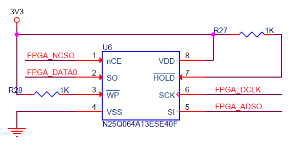
Configuration EEPROM
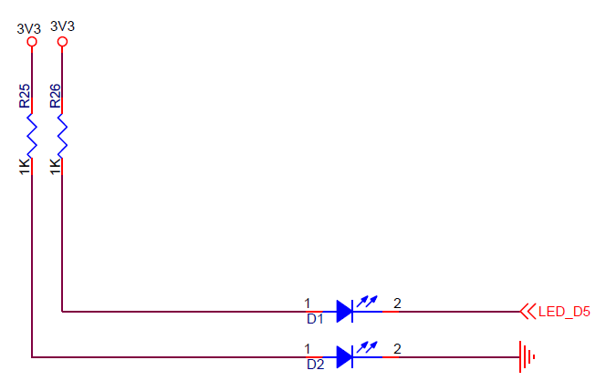
LEDs
- Power LED - D4 (On when 5V is applied)
- User LED - LED_D5 - FPGA Pin_L9 (pull low to illuminate LED)
Pushbuttons
- KEY0 - SW1 - FPGA Pin_F3
- RESET_N- SW2 - FPGA PIN_J6
- nCONFIG - SW3 - FPGA PIN_H5
SDRAM
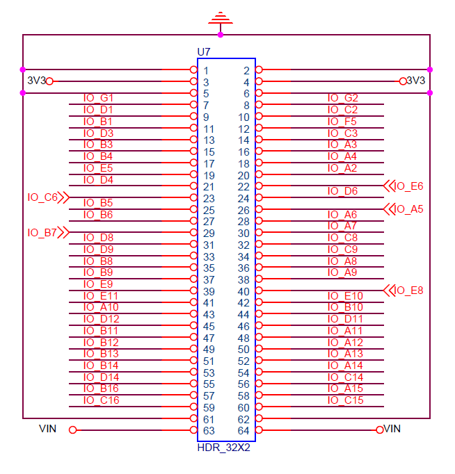
U7
U8
- Cannot place output or bidirectional pin J8IO[35] in input pin location M16
- Cannot place output or bidirectional pin J8IO[36] in input pin location M15
- Cannot place output or bidirectional pin J8IO[57] in input pin location E16
- Cannot place output or bidirectional pin J8IO[58] in input pin location E15
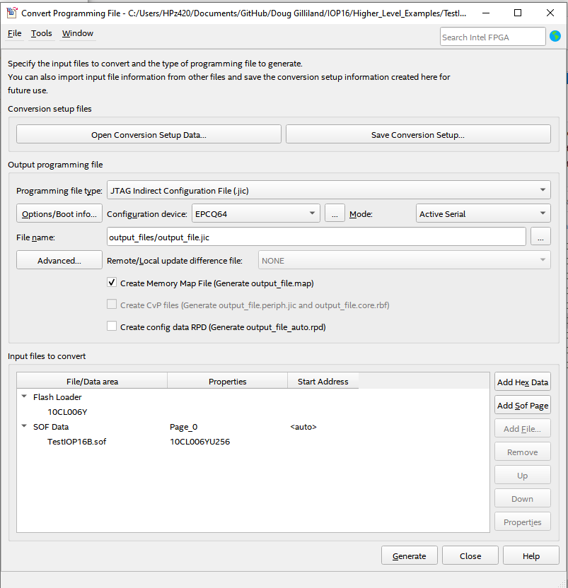
Programmer - Create jic file
- .jic file
- Device EPCQ64
- Active Serial
- Programming File Type: *.jic
- Advanced = Check both Disables...
- Select Flash Loader
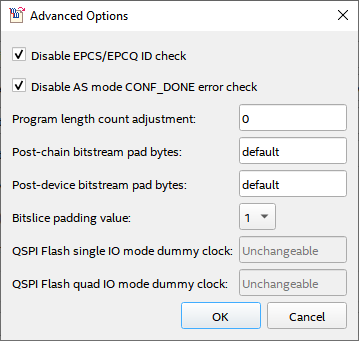
- Adv Options
- Click first 2 boxes
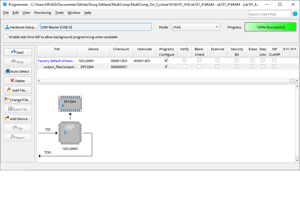
- Programmer
Pin List
- Used on RETRO-EP4CE15 card
| To | Direction | Location | I/O Standard | Pull-Up |
|---|---|---|---|---|
| cts1 | Input | PIN_D11 | 3.3-V LVTTL | |
| hSync | Output | PIN_D14 | 3.3-V LVTTL | |
| i_clk | Input | PIN_E1 | 3.3-V LVTTL | |
| i_key1 | Input | PIN_F3 | 3.3-V LVTTL | on |
| i_n_reset | Input | PIN_J6 | 3.3-V LVTTL | on |
| n_sdRamCas | Output | PIN_M7 | 3.3-V LVTTL | |
| n_sdRamCe | Output | PIN_P8 | 3.3-V LVTTL | |
| n_sdRamRas | Output | PIN_M8 | 3.3-V LVTTL | |
| n_sdRamWe | Output | PIN_P6 | 3.3-V LVTTL | |
| n_sRamCS | Output | PIN_E5 | 3.3-V LVTTL | |
| n_sRamOE | Output | PIN_A3 | 3.3-V LVTTL | |
| n_sRamWE | Output | PIN_B7 | 3.3-V LVTTL | |
| o_UsrLed | Output | PIN_L9 | 3.3-V LVTTL | |
| ps2Clk | Bidir | PIN_G1 | 3.3-V LVTTL | on |
| ps2Data | Bidir | PIN_G2 | 3.3-V LVTTL | on |
| rts1 | Output | PIN_B10 | 3.3-V LVTTL | |
| rxd1 | Input | PIN_D12 | 3.3-V LVTTL | |
| sdCS | Output | PIN_B16 | 3.3-V LVTTL | |
| sdMISO | Input | PIN_C15 | 3.3-V LVTTL | on |
| sdMOSI | Output | PIN_A15 | 3.3-V LVTTL | |
| sdRamAddr[14] | Output | PIN_L8 | 3.3-V LVTTL | |
| sdRamAddr[13] | Output | PIN_N8 | 3.3-V LVTTL | |
| sdRamAddr[12] | Output | PIN_T2 | 3.3-V LVTTL | |
| sdRamAddr[11] | Output | PIN_R3 | 3.3-V LVTTL | |
| sdRamAddr[10] | Output | PIN_T6 | 3.3-V LVTTL | |
| sdRamAddr[9] | Output | PIN_T3 | 3.3-V LVTTL | |
| sdRamAddr[8] | Output | PIN_R4 | 3.3-V LVTTL | |
| sdRamAddr[7] | Output | PIN_T4 | 3.3-V LVTTL | |
| sdRamAddr[6] | Output | PIN_R5 | 3.3-V LVTTL | |
| sdRamAddr[5] | Output | PIN_T5 | 3.3-V LVTTL | |
| sdRamAddr[4] | Output | PIN_R6 | 3.3-V LVTTL | |
| sdRamAddr[3] | Output | PIN_T8 | 3.3-V LVTTL | |
| sdRamAddr[2] | Output | PIN_R8 | 3.3-V LVTTL | |
| sdRamAddr[1] | Output | PIN_T7 | 3.3-V LVTTL | |
| sdRamAddr[0] | Output | PIN_R7 | 3.3-V LVTTL | |
| sdRamClk | Output | PIN_P2 | 3.3-V LVTTL | |
| sdRamClkEn | Output | PIN_R1 | 3.3-V LVTTL | |
| sdRamData[15] | Input | PIN_J2 | 3.3-V LVTTL | |
| sdRamData[14] | Input | PIN_J1 | 3.3-V LVTTL | |
| sdRamData[13] | Input | PIN_K2 | 3.3-V LVTTL | |
| sdRamData[12] | Input | PIN_K1 | 3.3-V LVTTL | |
| sdRamData[11] | Input | PIN_L2 | 3.3-V LVTTL | |
| sdRamData[10] | Input | PIN_L1 | 3.3-V LVTTL | |
| sdRamData[9] | Input | PIN_N1 | 3.3-V LVTTL | |
| sdRamData[8] | Input | PIN_N2 | 3.3-V LVTTL | |
| sdRamData[7] | Input | PIN_N5 | 3.3-V LVTTL | |
| sdRamData[6] | Input | PIN_P3 | 3.3-V LVTTL | |
| sdRamData[5] | Input | PIN_M6 | 3.3-V LVTTL | |
| sdRamData[4] | Input | PIN_N3 | 3.3-V LVTTL | |
| sdRamData[3] | Input | PIN_K6 | 3.3-V LVTTL | |
| sdRamData[2] | Input | PIN_L4 | 3.3-V LVTTL | |
| sdRamData[1] | Input | PIN_L3 | 3.3-V LVTTL | |
| sdRamData[0] | Input | PIN_K5 | 3.3-V LVTTL | |
| sdSCLK | Output | PIN_C16 | 3.3-V LVTTL | |
| serSelect | Input | |||
| sramAddress[19] | Output | PIN_D8 | 3.3-V LVTTL | |
| sramAddress[18] | Output | PIN_D9 | 3.3-V LVTTL | |
| sramAddress[17] | Output | PIN_B8 | 3.3-V LVTTL | |
| sramAddress[16] | Output | PIN_B9 | 3.3-V LVTTL | |
| sramAddress[15] | Output | PIN_E8 | 3.3-V LVTTL | |
| sramAddress[14] | Output | PIN_A9 | 3.3-V LVTTL | |
| sramAddress[13] | Output | PIN_A8 | 3.3-V LVTTL | |
| sramAddress[12] | Output | PIN_C9 | 3.3-V LVTTL | |
| sramAddress[11] | Output | PIN_C8 | 3.3-V LVTTL | |
| sramAddress[10] | Output | PIN_A7 | 3.3-V LVTTL | |
| sramAddress[9] | Output | PIN_A6 | 3.3-V LVTTL | |
| sramAddress[8] | Output | PIN_A4 | 3.3-V LVTTL | |
| sramAddress[7] | Output | PIN_C3 | 3.3-V LVTTL | |
| sramAddress[6] | Output | PIN_F5 | 3.3-V LVTTL | |
| sramAddress[5] | Output | PIN_C2 | 3.3-V LVTTL | |
| sramAddress[4] | Output | PIN_D1 | 3.3-V LVTTL | |
| sramAddress[3] | Output | PIN_B1 | 3.3-V LVTTL | |
| sramAddress[2] | Output | PIN_D3 | 3.3-V LVTTL | |
| sramAddress[1] | Output | PIN_B3 | 3.3-V LVTTL | |
| sramAddress[0] | Output | PIN_B4 | 3.3-V LVTTL | |
| sramData[7] | Bidir | PIN_A2 | 3.3-V LVTTL | |
| sramData[6] | Bidir | PIN_E6 | 3.3-V LVTTL | |
| sramData[5] | Bidir | PIN_D6 | 3.3-V LVTTL | |
| sramData[4] | Bidir | PIN_A5 | 3.3-V LVTTL | |
| sramData[3] | Bidir | PIN_B6 | 3.3-V LVTTL | |
| sramData[2] | Bidir | PIN_B5 | 3.3-V LVTTL | |
| sramData[1] | Bidir | PIN_C6 | 3.3-V LVTTL | |
| sramData[0] | Bidir | PIN_D4 | 3.3-V LVTTL | |
| txd1 | Output | PIN_A10 | 3.3-V LVTTL | |
| videoB0 | Output | PIN_B14 | 3.3-V LVTTL | |
| videoB1 | Output | PIN_A14 | 3.3-V LVTTL | |
| videoG0 | Output | PIN_B13 | 3.3-V LVTTL | |
| videoG1 | Output | PIN_A13 | 3.3-V LVTTL | |
| videoR0 | Output | PIN_B12 | 3.3-V LVTTL | |
| videoR1 | Output | PIN_A12 | 3.3-V LVTTL | |
| vSync | Output | PIN_C14 | 3.3-V LVTTL |
.qsf file
- Used on RETRO-EP4CE15 card
set_global_assignment -name FAMILY "Cyclone 10 LP"
set_global_assignment -name DEVICE 10CL006YU256C8G
set_global_assignment -name TOP_LEVEL_ENTITY uk101_41kRAM
set_global_assignment -name ORIGINAL_QUARTUS_VERSION "13.0 SP1"
set_global_assignment -name PROJECT_CREATION_TIME_DATE "14:00:12  MARCH 31, 2019"
set_global_assignment -name LAST_QUARTUS_VERSION "21.1.0 Lite Edition"
set_global_assignment -name PROJECT_OUTPUT_DIRECTORY output_files
set_global_assignment -name MIN_CORE_JUNCTION_TEMP 0
set_global_assignment -name MAX_CORE_JUNCTION_TEMP 85
set_global_assignment -name ERROR_CHECK_FREQUENCY_DIVISOR 1
set_global_assignment -name POWER_PRESET_COOLING_SOLUTION "23 MM HEAT SINK WITH 200 LFPM AIRFLOW"
set_global_assignment -name POWER_BOARD_THERMAL_MODEL "NONE (CONSERVATIVE)"
set_global_assignment -name STRATIX_DEVICE_IO_STANDARD "3.3-V LVTTL"
# Clock and reset
set_location_assignment PIN_E1 -to clk
set_location_assignment PIN_J6 -to n_reset
set_instance_assignment -name WEAK_PULL_UP_RESISTOR ON -to n_reset
# LEDs
# PS/2
set_location_assignment PIN_G1 -to ps2Clk
set_instance_assignment -name WEAK_PULL_UP_RESISTOR ON -to ps2Clk
set_location_assignment PIN_G2 -to ps2Data
set_instance_assignment -name WEAK_PULL_UP_RESISTOR ON -to ps2Data
# Serial
set_location_assignment PIN_D12 -to fpgaRx
set_instance_assignment -name WEAK_PULL_UP_RESISTOR ON -to fpgaRx
set_location_assignment PIN_A10 -to fpgaTx
set_location_assignment PIN_B10 -to fpgaRts
set_location_assignment PIN_D11 -to fpgaCts
# Video
set_location_assignment PIN_B12 -to vgaRedLo
set_location_assignment PIN_A12 -to vgaRedHi
set_location_assignment PIN_B13 -to vgaGrnLo
set_location_assignment PIN_A13 -to vgaGrnHi
set_location_assignment PIN_B14 -to vgaBluLo
set_location_assignment PIN_A14 -to vgaBluHi
set_location_assignment PIN_D14 -to vgaHsync
set_location_assignment PIN_C14 -to vgaVsync
# SD Card
set_location_assignment PIN_B16 -to sdCS
set_location_assignment PIN_C15 -to sdMISO
set_location_assignment PIN_A15 -to sdMOSI
set_instance_assignment -name WEAK_PULL_UP_RESISTOR ON -to sdMISO
set_location_assignment PIN_C16 -to sdSCLK
# SRAM
set_location_assignment PIN_E5 -to n_sRamCS
set_location_assignment PIN_A3 -to n_sRamOE
set_location_assignment PIN_B7 -to n_sRamWE
set_location_assignment PIN_D4 -to sramData[0]
set_location_assignment PIN_C6 -to sramData[1]
set_location_assignment PIN_B5 -to sramData[2]
set_location_assignment PIN_B6 -to sramData[3]
set_location_assignment PIN_A5 -to sramData[4]
set_location_assignment PIN_D6 -to sramData[5]
set_location_assignment PIN_E6 -to sramData[6]
set_location_assignment PIN_A2 -to sramData[7]
set_location_assignment PIN_B4 -to sramAddress[0]
set_location_assignment PIN_B3 -to sramAddress[1]
set_location_assignment PIN_D3 -to sramAddress[2]
set_location_assignment PIN_B1 -to sramAddress[3]
set_location_assignment PIN_D1 -to sramAddress[4]
set_location_assignment PIN_C2 -to sramAddress[5]
set_location_assignment PIN_F5 -to sramAddress[6]
set_location_assignment PIN_C3 -to sramAddress[7]
set_location_assignment PIN_A4 -to sramAddress[8]
set_location_assignment PIN_A6 -to sramAddress[9]
set_location_assignment PIN_A7 -to sramAddress[10]
set_location_assignment PIN_C8 -to sramAddress[11]
set_location_assignment PIN_C9 -to sramAddress[12]
set_location_assignment PIN_A8 -to sramAddress[13]
set_location_assignment PIN_A9 -to sramAddress[14]
set_location_assignment PIN_E8 -to sramAddress[15]
set_location_assignment PIN_B9 -to sramAddress[16]
set_location_assignment PIN_B8 -to sramAddress[17]
set_location_assignment PIN_D9 -to sramAddress[18]
set_location_assignment PIN_D8 -to sramAddress[19]
#
set_location_assignment PIN_T10 -to IO_PIN[3]
set_location_assignment PIN_R10 -to IO_PIN[4]
set_location_assignment PIN_T11 -to IO_PIN[5]
set_location_assignment PIN_R11 -to IO_PIN[6]
set_location_assignment PIN_T12 -to IO_PIN[7]
set_location_assignment PIN_R12 -to IO_PIN[8]
set_location_assignment PIN_M9 -to IO_PIN[9]
set_location_assignment PIN_N9 -to IO_PIN[10]
set_location_assignment PIN_P9 -to IO_PIN[11]
set_location_assignment PIN_M10 -to IO_PIN[12]
set_location_assignment PIN_N11 -to IO_PIN[13]
set_location_assignment PIN_P11 -to IO_PIN[14]
set_location_assignment PIN_T13 -to IO_PIN[15]
set_location_assignment PIN_R13 -to IO_PIN[16]
set_location_assignment PIN_T14 -to IO_PIN[17]
set_location_assignment PIN_T15 -to IO_PIN[18]
set_location_assignment PIN_M11 -to IO_PIN[19]
set_location_assignment PIN_N12 -to IO_PIN[20]
set_location_assignment PIN_N13 -to IO_PIN[21]
set_location_assignment PIN_R14 -to IO_PIN[22]
set_location_assignment PIN_P14 -to IO_PIN[23]
set_location_assignment PIN_N14 -to IO_PIN[24]
set_location_assignment PIN_R16 -to IO_PIN[25]
set_location_assignment PIN_P16 -to IO_PIN[26]
set_location_assignment PIN_N15 -to IO_PIN[27]
set_location_assignment PIN_N16 -to IO_PIN[28]
set_location_assignment PIN_M15 -to IO_PIN[29]
set_location_assignment PIN_M16 -to IO_PIN[30]
set_location_assignment PIN_L15 -to IO_PIN[31]
set_location_assignment PIN_L16 -to IO_PIN[32]
set_location_assignment PIN_M12 -to IO_PIN[33]
set_location_assignment PIN_P15 -to IO_PIN[34]
set_location_assignment PIN_L13 -to IO_PIN[35]
set_location_assignment PIN_L14 -to IO_PIN[36]
set_location_assignment PIN_K15 -to IO_PIN[37]
set_location_assignment PIN_K16 -to IO_PIN[38]
set_location_assignment PIN_J12 -to IO_PIN[39]
set_location_assignment PIN_K12 -to IO_PIN[40]
set_location_assignment PIN_J13 -to IO_PIN[41]
set_location_assignment PIN_J14 -to IO_PIN[42]
set_location_assignment PIN_J11 -to IO_PIN[43]
set_location_assignment PIN_K11 -to IO_PIN[44]
set_location_assignment PIN_F11 -to IO_PIN[45]
set_location_assignment PIN_G11 -to IO_PIN[46]
set_location_assignment PIN_F14 -to IO_PIN[47]
set_location_assignment PIN_F13 -to IO_PIN[48]
# SDRAM
set_location_assignment PIN_P2 -to sdRamClk
set_location_assignment PIN_R1 -to sdRamClkEn
set_location_assignment PIN_M7 -to n_sdRamCas
set_location_assignment PIN_P8 -to n_sdRamCe
set_location_assignment PIN_M8 -to n_sdRamRas
set_location_assignment PIN_P6 -to n_sdRamWe
set_location_assignment PIN_R7 -to sdRamAddr[0]
set_location_assignment PIN_T7 -to sdRamAddr[1]
set_location_assignment PIN_R8 -to sdRamAddr[2]
set_location_assignment PIN_T8 -to sdRamAddr[3]
set_location_assignment PIN_R6 -to sdRamAddr[4]
set_location_assignment PIN_T5 -to sdRamAddr[5]
set_location_assignment PIN_R5 -to sdRamAddr[6]
set_location_assignment PIN_T4 -to sdRamAddr[7]
set_location_assignment PIN_R4 -to sdRamAddr[8]
set_location_assignment PIN_T3 -to sdRamAddr[9]
set_location_assignment PIN_T6 -to sdRamAddr[10]
set_location_assignment PIN_R3 -to sdRamAddr[11]
set_location_assignment PIN_T2 -to sdRamAddr[12]
set_location_assignment PIN_N8 -to sdRamAddr[13]
set_location_assignment PIN_L8 -to sdRamAddr[14]
set_location_assignment PIN_K5 -to sdRamData[0]
set_location_assignment PIN_L3 -to sdRamData[1]
set_location_assignment PIN_L4 -to sdRamData[2]
set_location_assignment PIN_K6 -to sdRamData[3]
set_location_assignment PIN_N3 -to sdRamData[4]
set_location_assignment PIN_M6 -to sdRamData[5]
set_location_assignment PIN_P3 -to sdRamData[6]
set_location_assignment PIN_N5 -to sdRamData[7]
set_location_assignment PIN_N2 -to sdRamData[8]
set_location_assignment PIN_N1 -to sdRamData[9]
set_location_assignment PIN_L1 -to sdRamData[10]
set_location_assignment PIN_L2 -to sdRamData[11]
set_location_assignment PIN_K1 -to sdRamData[12]
set_location_assignment PIN_K2 -to sdRamData[13]
set_location_assignment PIN_J1 -to sdRamData[14]
set_location_assignment PIN_J2 -to sdRamData[15]
