Difference between revisions of "PiPicoMite02 Based Test Station"
Jump to navigation
Jump to search
Blwikiadmin (talk | contribs) |
Blwikiadmin (talk | contribs) |
||
| (One intermediate revision by the same user not shown) | |||
| Line 22: | Line 22: | ||
* DB-37 to connect to external test cards | * DB-37 to connect to external test cards | ||
| − | == LED-32 Card == | + | === LED-32 Card === |
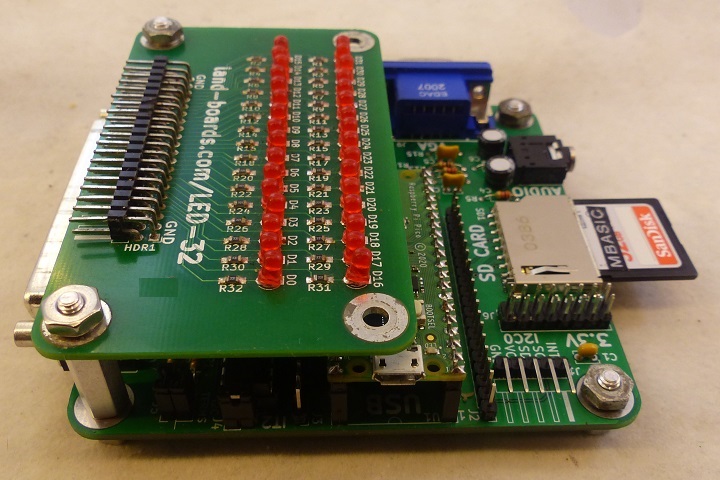
[[file:LED-32-P426-720px.jpg]] | [[file:LED-32-P426-720px.jpg]] | ||
| Line 33: | Line 33: | ||
* USB on Pico | * USB on Pico | ||
| + | ** Not required if VGA, PS/2 are used | ||
** Used to download code | ** Used to download code | ||
** Alternate way to power the card | ** Alternate way to power the card | ||
| − | ** Can also run tests over this connection | + | ** Can also run tests over this connection (mirrors PS/2, VGA) |
| − | |||
* [[LED-32]] 40-pin connector to monitor outputs from Digital I/O cards | * [[LED-32]] 40-pin connector to monitor outputs from Digital I/O cards | ||
| − | * | + | * J1 - I2C to UUT |
| − | * VGA | + | * J8 - Audio |
| − | * PS/2 | + | * J9 - VGA |
| + | * J10 - USB Power | ||
| + | * J11 - PS/2 | ||
| + | * P1 - DB-37 provides 32-bits of Digital I/O | ||
== Card stackup == | == Card stackup == | ||
Latest revision as of 13:21, 21 June 2022
Contents
Hardware
- PiPicoMite02 Processor Card
- LED-32
- UUT Cables Set
- PS/2 keyboard
- VGA Monitor
- SD card with Test Code
- 5V into USB B or power card with USB Micro on Pico
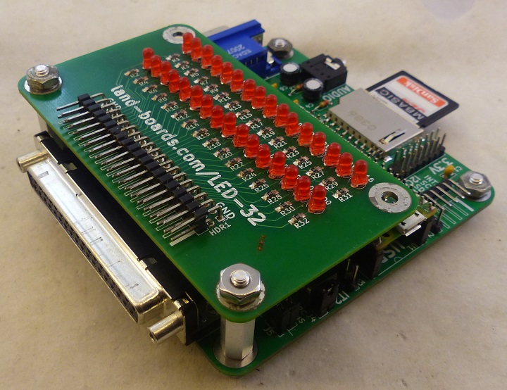
- (4) Short standoffs below PiPicoMite02 Processor Card
- (2) "Medium" standoffs on end of board with DB-37
- LED-32 mounted above PiPicoMite02 Processor Card
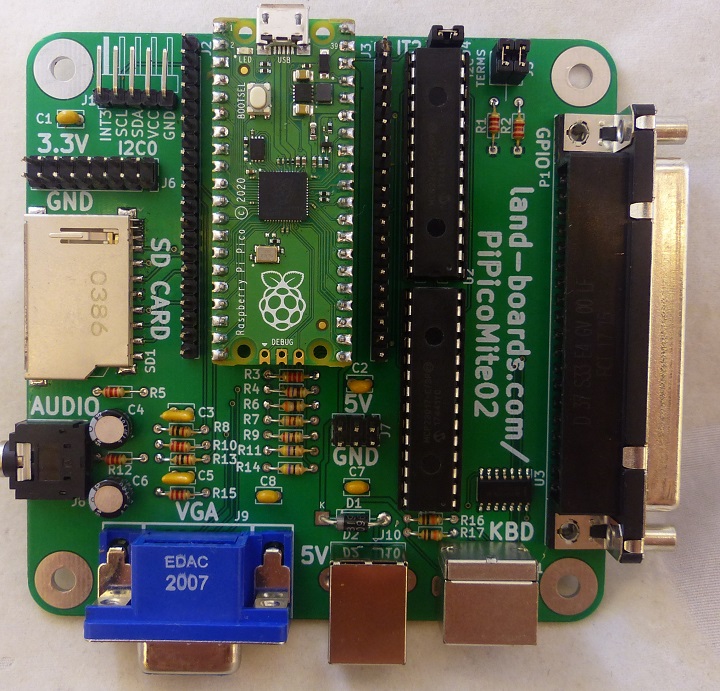
PiPicoMite02 Processor Card
- Test code is stored on SD Card
- External I2C cards connect to J1 - I2C0 connector
- DB-37 to connect to external test cards
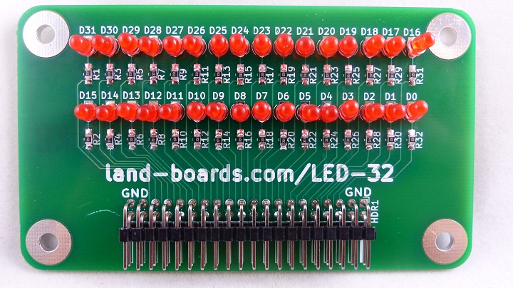
LED-32 Card
- 32 LEDs
- 8 Ground pins
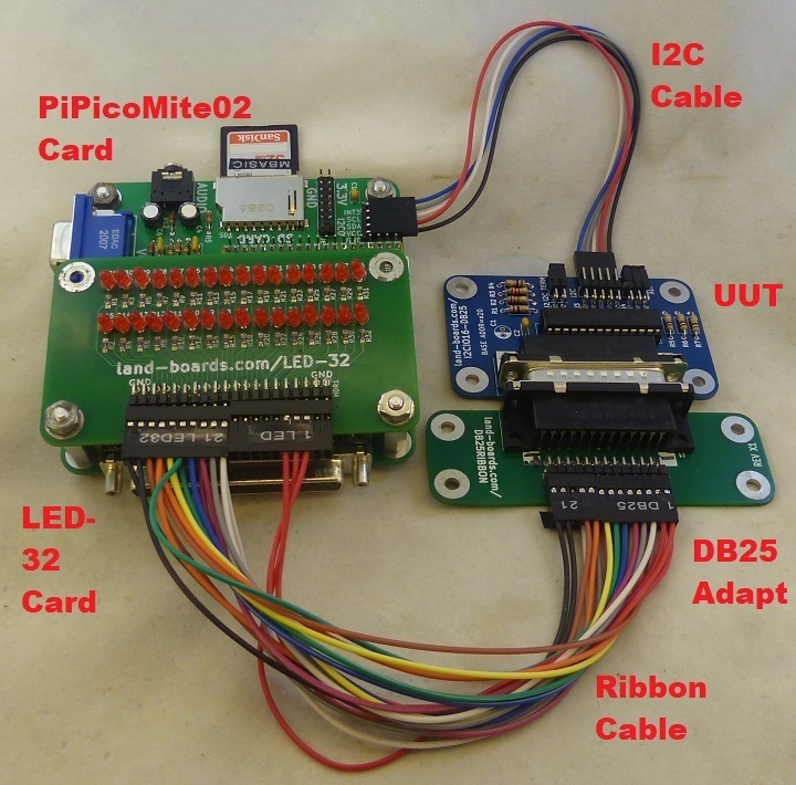
- Connect with Ribbon Cables
Test Station Connectors
- USB on Pico
- Not required if VGA, PS/2 are used
- Used to download code
- Alternate way to power the card
- Can also run tests over this connection (mirrors PS/2, VGA)
- LED-32 40-pin connector to monitor outputs from Digital I/O cards
- J1 - I2C to UUT
- J8 - Audio
- J9 - VGA
- J10 - USB Power
- J11 - PS/2
- P1 - DB-37 provides 32-bits of Digital I/O
Card stackup
- 6-32 standoffs
Cable Sets
- Ribbon cables
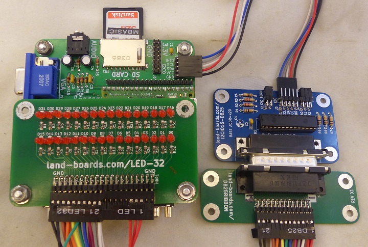
- Connect directly to LED-32 card or to DB37RIBBON card(s)
- UUT is I2CIO16-DB25 example
Program UUT EEPROM
- Some UUTs have Personality EEPROMs
- Run
chdir "/lbcards/ODAS_EEPROM"
load "ODASEEPROM.bas"
run
- Typical response if the card is already programmed
Found device at 0x50
Personality EEPROM contents
 Signature = ODAS
 Version = 1
 Rsvd = 0
 NumAtoms = 2
 eeplen = 96
 uuid = 0000000000000000
 Product ID = 6 (DIGIO32-I2C)
 vslen = 32
 pslen = 32
 Vendor String = LAND-BOARDS.COM
 Product String = DIGIO32-I2C
Re-write (Y/N)?
Test Station Validation / Self-Test
- PiPicoMite02 Test Station cards
- DB37RIBBON card
- Cable set
- Same cable set used with DIGIO32-I2C
- (2) 10x2 ribbon cables
- Marking 1 DB37, 21 DB38 on one end, 1 LED32, 21 LED32 on the other end
- GPIO32-01.bas - test software
- Bounces a bit across the LEDs
- Type
chdir "/lbcards/GPIO32"
load "GPIO32-01.bas"
run
- Will do 55, aa pattern alternating
- Will bounce a bit across the LEDs
- Hit any key to contines
Views
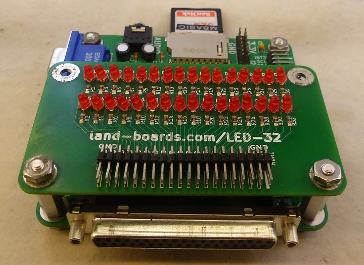
- Front view
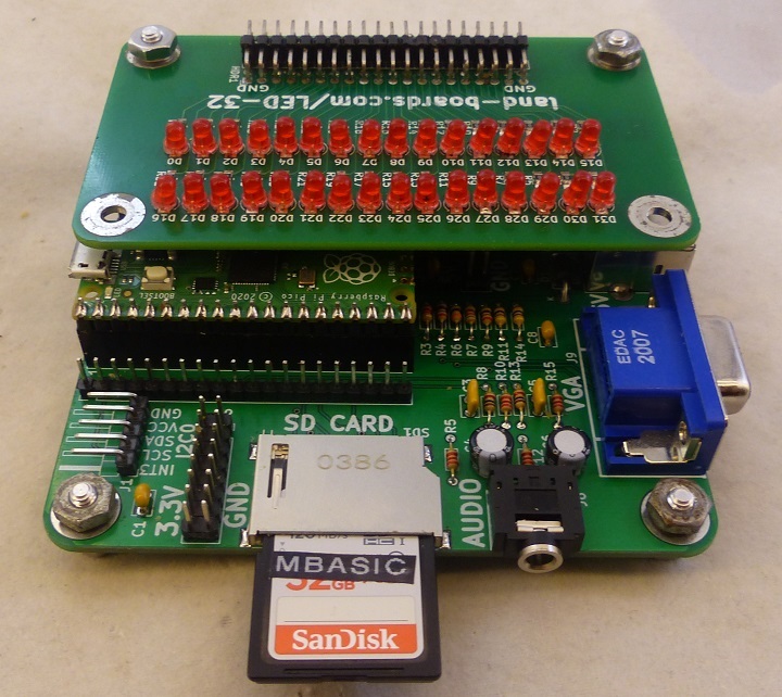
- Rear view
- VGA, PS/2, USB Power side view
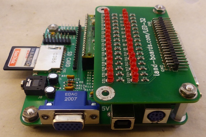
- Pico USB and External I2C connection side view
