Difference between revisions of "OptoFastBi"
Jump to navigation
Jump to search
Blwikiadmin (talk | contribs) |
Blwikiadmin (talk | contribs) |
||
| (2 intermediate revisions by the same user not shown) | |||
| Line 1: | Line 1: | ||
| + | [[File:tindie-mediums.png|link=https://www.tindie.com/products/land_boards/two-optos-in-two-directions-optofastbi/]] | ||
| + | |||
| + | [[File:OptoFastBi-P672-720px.jpg]] | ||
| + | |||
== Features == | == Features == | ||
| Line 15: | Line 19: | ||
* 49x49mm | * 49x49mm | ||
* (4) 4-40 mounting holes | * (4) 4-40 mounting holes | ||
| + | |||
| + | == Assembly Sheet == | ||
| + | |||
| + | * [[OptoFastBi Assembly Sheet]] | ||
Latest revision as of 23:56, 29 December 2019
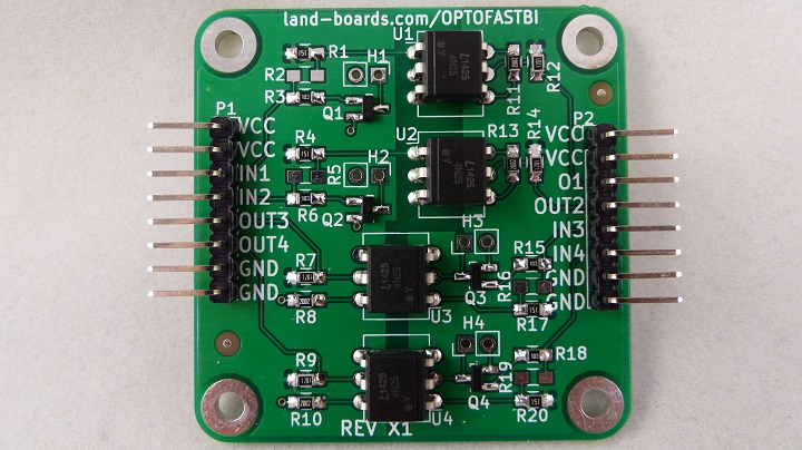
Features
- 4-Channel Opto-Isolator card
- 2-Channels in each direction
- 4N25 Optoisolators
- Input /Output isolation
- Transistor driver for Opto LED reduces required drive from 20 mA to under 500 uA
- 5V Input channels share their own common VCC/Ground
- 5V Output channels share their own common Vcc/Ground
- 8-pin headers for input/output
- Configuration Options
- Speed enhanced
- Bypass Input transistors
- Remove Output collector resistors
- 49x49mm
- (4) 4-40 mounting holes

