Difference between revisions of "RPPSOC"
Jump to navigation
Jump to search
Blwikiadmin (talk | contribs) |
Blwikiadmin (talk | contribs) |
||
| (26 intermediate revisions by the same user not shown) | |||
| Line 101: | Line 101: | ||
== Factory Test Procedure == | == Factory Test Procedure == | ||
| − | + | * Overview of test Procedures | |
| + | |||
| + | # Program Hat EEPROM on UUT | ||
| + | # Test Card using Raspberry Pi and PSOC code | ||
| + | # Load/Verify Shipping Program | ||
| + | |||
| + | === Test Setup === | ||
* Unit Under Test (UUT) | * Unit Under Test (UUT) | ||
| − | * Raspberry Pi | + | * Raspberry Pi |
| − | * [[LED- | + | * (2) [[LED-TEST-2]] Cards attached to UUT J3, J4 |
* Cables set | * Cables set | ||
| − | |||
| − | |||
| − | [[file:RPPSOC- | + | === Program Hat EEPROM on UUT === |
| + | |||
| + | * Can program EEPROM using [[RPI_PSOC5]] running [https://github.com/douggilliland/RPI_PSOC5/tree/master/RPI_PSOC5_Serial_01 RPI_PSOC5_Serial_01] | ||
| + | * '2' to select RPPSOC | ||
| + | * 'W' to write EEPROM | ||
| + | * 'R' to read back EEPROM | ||
| + | |||
| + | === Test Card using Raspberry Pi and PSOC code === | ||
| + | |||
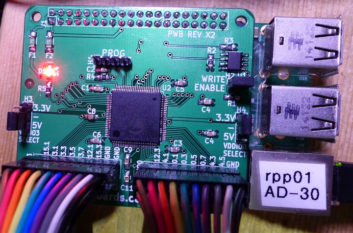
| + | [[FILE:RPPSOC_TEST_P110153-720PX.JPG]] | ||
| + | |||
| + | * Download [https://github.com/land-boards/LB-RPPSOC/tree/master/RPPSOC-FAT-Chain.cydsn RPPSOC-FAT-Chain] to RPPSOC using KitProg from PSoC Creator | ||
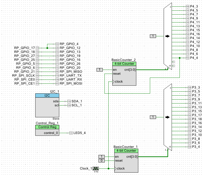
| + | * Description of the [https://github.com/land-boards/LB-RPPSOC/tree/master/RPPSOC-FAT-Chain.cydsn RPPSOC-FAT-Chain] logic inside PSoC | ||
| + | ** Blinks LEDs attached to J3, J4 in a "circular" pattern | ||
| + | ** Loops back pins to Raspberry Pi | ||
| + | *** "Distant" pins are tested in pairs so pin shorts would be found | ||
| + | |||
| + | [[file:RPPSOC_PSoC_FAT_SCHEMATIC.PNG]] | ||
| + | |||
| + | * On Raspberry Pi, run [https://github.com/land-boards/LB-RPPSOC/tree/master/TestCode fastTests-RPPSOC.py] | ||
| + | |||
| + | <pre> | ||
| + | cd ~/RPPSOC/TestCodePi/ | ||
| + | sudo python ./fastTests-RPP-SOC.py | ||
| + | </pre> | ||
| + | |||
| + | * Verify all J3/J4 LEDs are displayed one at a time | ||
| + | * Loopback test repeats 100x | ||
| + | * Result should be | ||
| + | |||
| + | <pre> | ||
| + | Passed 100 loop test | ||
| + | </pre> | ||
| + | |||
| + | === Load/Verify Shipping Program === | ||
| + | |||
| + | * Program UUT with Shipment code [https://github.com/land-boards/LB-RPPSOC/tree/master/RPPSOC-Blink2.cydsn RPPSOC-Blink2] | ||
| + | * I/O pins (to Raspberry Pi and J3/J4) are not assigned so they don't conflict with external hardware or Host Raspberry Pi pins | ||
| + | * PSoC CPU code blinks on-board LED | ||
| + | ** Demonstrates that the CPU is running code | ||
| + | * When board is received by customer, the on-board LED should be blinking | ||
== Drivers/Example Code == | == Drivers/Example Code == | ||
Latest revision as of 11:19, 7 October 2022
Contents
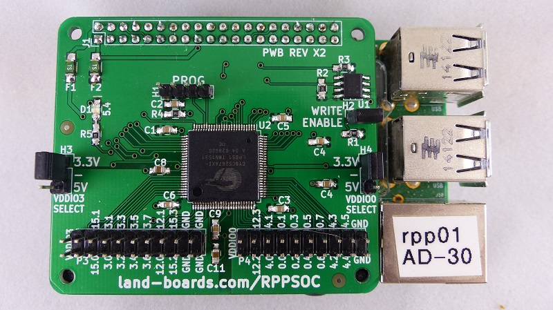
Raspberry Pi System-on-a-Chip
Features
- PSOC part CY8C5267AXI-LP051
- Core: ARM Cortex M3
- Data Bus Width: 32 bit
- Maximum Clock Frequency: 67 MHz
- Program Memory Size: 128 kB
- Data RAM Size: 32 kB
- ADC Resolution: 12 bit
- Data RAM Type: SRAM
- Interface Type: I2C, USB
- Number of ADC Channels: 1
- Number of I/Os: 72 I/O
- Number of Timers/Counters: 4 Timer
- Program Memory Type: Flash
- Works on all Raspberry Pi cards with 40 pin GPIO (A+/B+/Pi2/Pi3/Zero)
- All 29 Raspberry Pi I/O lines are connected to the PSOC
- 3 of the lines are used for programming the PSSoC
- Configuration EEPROM
- Fuses on 3.3V and 5V power
- Two I/O connectors
- 14 + 16 = 30 I/O pins
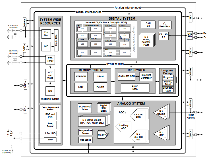
PSoC Architecture
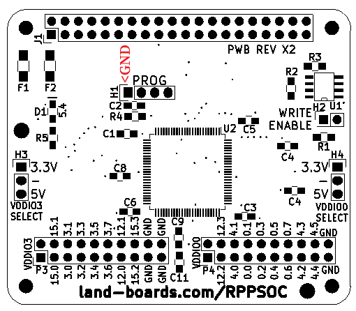
Headers / Connectors
- Card marking
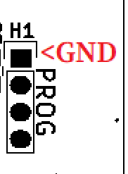
H1 - Programming Header
- Can program the card via this connector
- I use the KitProg part of CY8CKIT-059 with a 4-pin cable wired 1:1
- Note orientation of pin 1
H2 - EEPROM Write Enable
- Install jumper on header to program EEPROM from Raspberry Pi
- Remove jumper to write Protect EEPROM
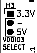
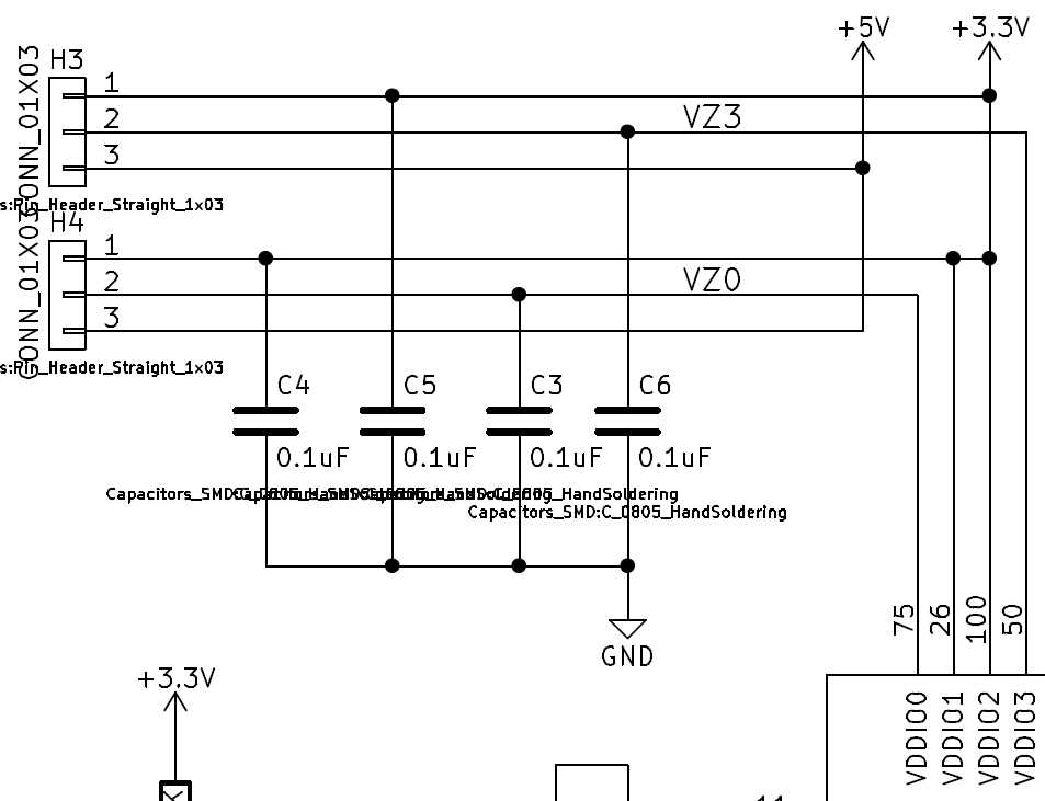
H3/H4 - I/O Voltage Select
- Select the I/O voltage on P3, P4 output connectors
- 3.3 or 5V
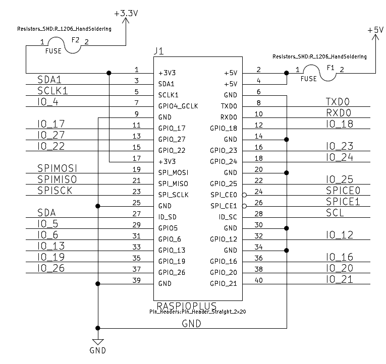
J1 - Raspberry Pi GPIO Connector
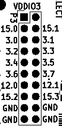
P3 - I/O connector
- Header indicates PSoC port
- Schematic indicates PSoC pin number
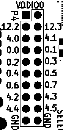
P4 - I/O connector
- Header indicates PSoC port
- Schematic indicates PSoC pin number
Schematic
Factory Test Procedure
- Overview of test Procedures
- Program Hat EEPROM on UUT
- Test Card using Raspberry Pi and PSOC code
- Load/Verify Shipping Program
Test Setup
- Unit Under Test (UUT)
- Raspberry Pi
- (2) LED-TEST-2 Cards attached to UUT J3, J4
- Cables set
Program Hat EEPROM on UUT
- Can program EEPROM using RPI_PSOC5 running RPI_PSOC5_Serial_01
- '2' to select RPPSOC
- 'W' to write EEPROM
- 'R' to read back EEPROM
Test Card using Raspberry Pi and PSOC code
- Download RPPSOC-FAT-Chain to RPPSOC using KitProg from PSoC Creator
- Description of the RPPSOC-FAT-Chain logic inside PSoC
- Blinks LEDs attached to J3, J4 in a "circular" pattern
- Loops back pins to Raspberry Pi
- "Distant" pins are tested in pairs so pin shorts would be found
- On Raspberry Pi, run fastTests-RPPSOC.py
cd ~/RPPSOC/TestCodePi/
sudo python ./fastTests-RPP-SOC.py
- Verify all J3/J4 LEDs are displayed one at a time
- Loopback test repeats 100x
- Result should be
Passed 100 loop test
Load/Verify Shipping Program
- Program UUT with Shipment code RPPSOC-Blink2
- I/O pins (to Raspberry Pi and J3/J4) are not assigned so they don't conflict with external hardware or Host Raspberry Pi pins
- PSoC CPU code blinks on-board LED
- Demonstrates that the CPU is running code
- When board is received by customer, the on-board LED should be blinking
Drivers/Example Code
- LB-RPPSOC GitHub Repo
- RPPSOC GitHub Repo
- HSSP_Programmer - Code that programs PSoC from the Raspberry Pi (.o files)
- EEPROM file - Data in the On-Board EEPROM
Programming PSoC from the Raspberry Pi
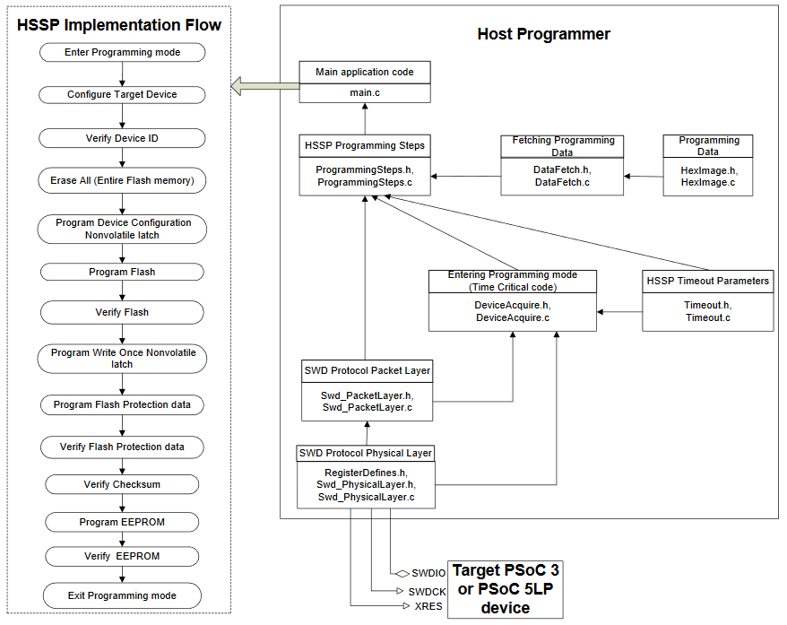
- Program the PSoC from the Raspberry Pi using Host Sourced Serial Programming
- Flow
Connections between Raspberry Pi and RPPSOC
| Programmer | H1 pin | Python IO Pin | Pi connector pin | WiringPi IO Pin |
|---|---|---|---|---|
| RESET | H1-3 | IO_22(Python) | Pi Pin 15 | GPIO.3(WiringPi) |
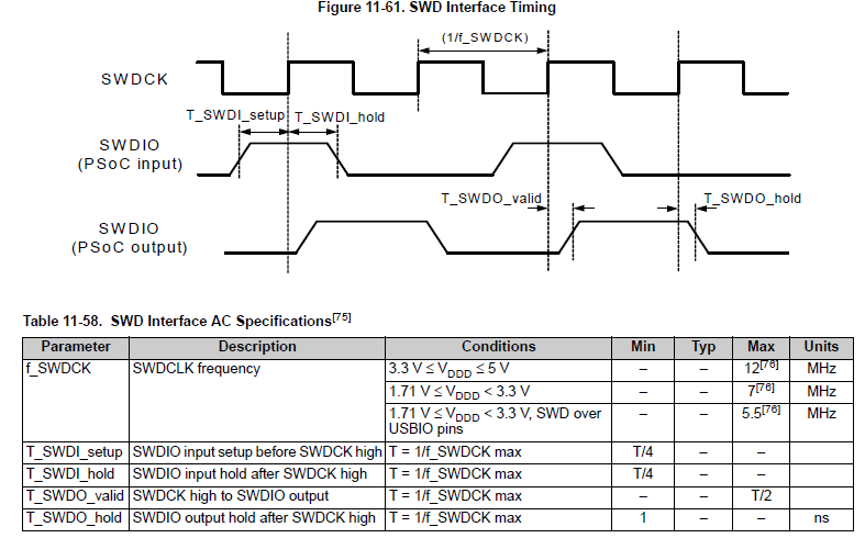
| SWDCLK | H1-4 | IO_23(Python) | Pi Pin 16 | GPIO.4(WiringPi) |
| SWDIO | H1-6 | IO_25(Python) | Pi Pin 17 | GPIO.5(WiringPi) |

