Difference between revisions of "ER-MIDI-THRU"
Jump to navigation
Jump to search
Blwikiadmin (talk | contribs) |
Blwikiadmin (talk | contribs) |
||
| (39 intermediate revisions by the same user not shown) | |||
| Line 1: | Line 1: | ||
| − | [[FILE:ER-MIDI- | + | [[FILE:ER-MIDI-THRU_SET_CCA_Front_Back-002-720px.jpg]] |
| + | == Features == | ||
| + | |||
| + | * Splits MIDI from input to 4 outputs | ||
| + | * MIDI channel agnostic | ||
| + | ** Passes through all MIDI messages received | ||
| + | * Pairs nicely with [[ER-MIDI-CV4-02]] card using stereo 3.5mm patch cable | ||
* MIDI In on DIN-5 or 3.5mm TRS Type A | * MIDI In on DIN-5 or 3.5mm TRS Type A | ||
| + | ** Can only plug in one at a time | ||
| + | ** MIDI spec uses 2.5mm jack but allows for other sizes such as 2.5mm | ||
* 4 Channel MIDI outputs on 3.5mm TRS Type A | * 4 Channel MIDI outputs on 3.5mm TRS Type A | ||
| − | * Activity LED | + | * MIDI Activity LED |
| − | * 6 HP wide (30mm) | + | ** ON when a MIDI packet is input |
| − | ** Daughtercard is 28mm for easy installation | + | * Front Panel is 6 HP wide (30mm) |
| + | ** Daughtercard is 28mm wide for easy installation into rack | ||
* 3U tall | * 3U tall | ||
| − | * Eurorack power jack | + | * Eurorack 2x8 power jack |
| − | ** Uses 5V | + | ** Uses 5V only |
| + | |||
| + | == Connectors== | ||
| + | |||
| + | === MIDI TRS A === | ||
| + | |||
| + | * From [https://minimidi.world/ minimidi.world] | ||
| + | * DIN | ||
| + | |||
| + | [[file:MINIMIDI_WORLD_DIN.PNG]] | ||
| + | |||
| + | * TRS A | ||
| + | |||
| + | [[file:MINIMIDI_WORLD_TYPE-A.PNG]] | ||
| + | |||
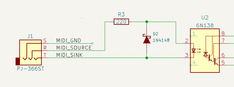
| + | === J1 - MIDI In - TRS === | ||
| + | |||
| + | [[FILE:ER-MIDI-THRU_J1_MIDI-IN_TRS.PNG]] | ||
| + | |||
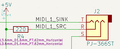
| + | === J2-J5 - MIDI In - TRS === | ||
| + | |||
| + | [[FILE:ER-MIDI-THRU_J2-J5_MIDI-OUT_TRS.PNG]] | ||
| + | |||
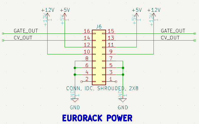
| + | === J6 - Eurorack Power === | ||
| + | |||
| + | * 2x8 IDC connector | ||
| + | * Requires 5V power | ||
| + | ** Only uses +5V and GND | ||
| + | ** Does not use +/-12V, GATE, or CV | ||
| + | |||
| + | [[FILE:ER-MIDI-THRU_J6_EURORACK-PWR.PNG]] | ||
| + | |||
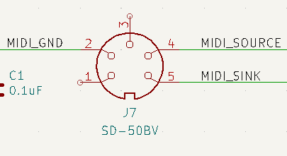
| + | === J7 - MIDI In - DIN === | ||
| + | |||
| + | * Through hole vertical mount DIN connector | ||
| + | ** DIN connector stands proud from Front Panel by a small amount | ||
| + | |||
| + | [[FILE:ER-MIDI-THRU_J7_MIDI_DIN.PNG]] | ||
| + | |||
| + | == Design == | ||
| + | |||
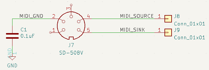
| + | * MIDI In DIN | ||
| + | |||
| + | [[file:ER-MIDI-THRU_MIDI-IN_DIN.PNG]] | ||
| + | |||
| + | * MIDI In TRS-A | ||
| + | |||
| + | [[file:ER-MIDI-THRU_MIDI-IN_TRS-A.PNG]] | ||
| + | |||
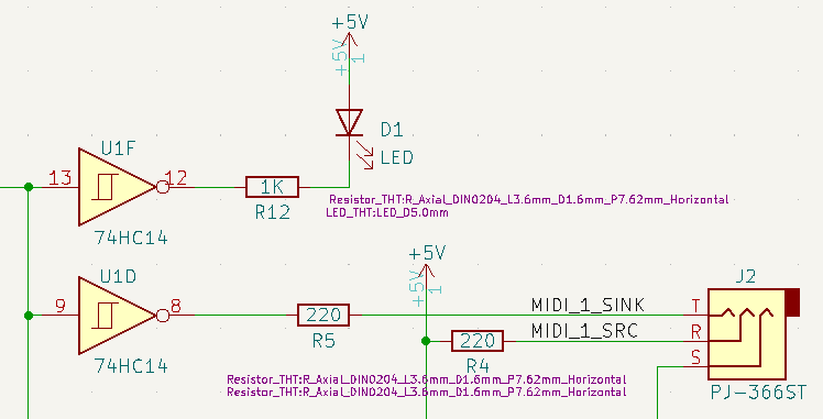
| + | * MIDI Out TRS-A | ||
| + | |||
| + | [[file:ER-MIDI-THRU_MIDI-OUT_TRS-A.PNG]] | ||
== Daughtercard == | == Daughtercard == | ||
| − | [[FILE:ER-MIDI- | + | * Daughtercard is 110mm tall |
| + | ** 9.5mm clearance at top | ||
| + | ** 9mm clearance at bottom | ||
| + | |||
| + | [[FILE:ER-MIDI-THRU_SET_P1080705-720px.jpg]] | ||
== Reference Documents == | == Reference Documents == | ||
| − | * Deftaudio | + | * [https://www.midi.org/specifications/midi-transports-specifications/specification-for-use-of-trs-connectors-with-midi-devices-2 RP-054] - Specification for use of TRS Connectors with MIDI Devices |
| + | * From the page [https://www.morningstar.io/post/all-you-need-to-know-about-trs-midi-connections#:~:text=Type%20A%20The%20Type%20A%20TRS%20connection%20is,line%20down%29%20and%20the%20Ring%20is%20the%20Source. All you need to know about TRS MIDI connections] | ||
| + | |||
| + | <PRE> | ||
| + | The SOURCE provides the power, whether 3.3v or 5v, to power an LED in the optocoupler in the receiving device, | ||
| + | while the SINK pulls that power to ground whenever there is data to be transmitted. | ||
| + | |||
| + | DIN MIDI Connector | ||
| + | In the good old DIN5 MIDI Connectors, 3 out of the 5 pins are used. Pin 2 is used as GROUND, | ||
| + | Pin 4 is used as the current SOURCE, while Pin 5 is used as the current SINK. | ||
| + | |||
| + | Type A | ||
| + | The Type A TRS connection is the official standard adopted by the MIDI Association. The Tip is the Sink (pulls the data line down) and the Ring is the Source. | ||
| + | </PRE> | ||
| + | |||
| + | * Deftaudio example | ||
** [https://github.com/Deftaudio/Midi-boards/blob/master/Eurorack_MIDIThru4_TRS/Eurorack_MIDIThru4_TRS_sch.pdf TRS version] | ** [https://github.com/Deftaudio/Midi-boards/blob/master/Eurorack_MIDIThru4_TRS/Eurorack_MIDIThru4_TRS_sch.pdf TRS version] | ||
** [https://github.com/Deftaudio/Midi-boards/blob/master/Eurorack_MIDIThru4_DIN/Eurorack_MIDIThru4_DIN_sch.pdf DIN version] | ** [https://github.com/Deftaudio/Midi-boards/blob/master/Eurorack_MIDIThru4_DIN/Eurorack_MIDIThru4_DIN_sch.pdf DIN version] | ||
| Line 22: | Line 101: | ||
== Assembly Sheet == | == Assembly Sheet == | ||
| − | [[ER-MIDI-THRU Rev 1 Assembly Sheet]] | + | * [http://land-boards.com/ER-MIDI-THRU/ER-MIDI-THRU-DB_Rev1_ibom.html ER-MIDI-THRU Rev 1 Interactive BOM] |
| + | * [[ER-MIDI-THRU Rev 1 Assembly Sheet]] | ||
Latest revision as of 22:01, 9 March 2023
Contents
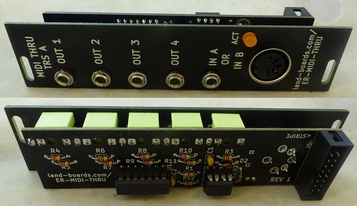
Features
- Splits MIDI from input to 4 outputs
- MIDI channel agnostic
- Passes through all MIDI messages received
- Pairs nicely with ER-MIDI-CV4-02 card using stereo 3.5mm patch cable
- MIDI In on DIN-5 or 3.5mm TRS Type A
- Can only plug in one at a time
- MIDI spec uses 2.5mm jack but allows for other sizes such as 2.5mm
- 4 Channel MIDI outputs on 3.5mm TRS Type A
- MIDI Activity LED
- ON when a MIDI packet is input
- Front Panel is 6 HP wide (30mm)
- Daughtercard is 28mm wide for easy installation into rack
- 3U tall
- Eurorack 2x8 power jack
- Uses 5V only
Connectors
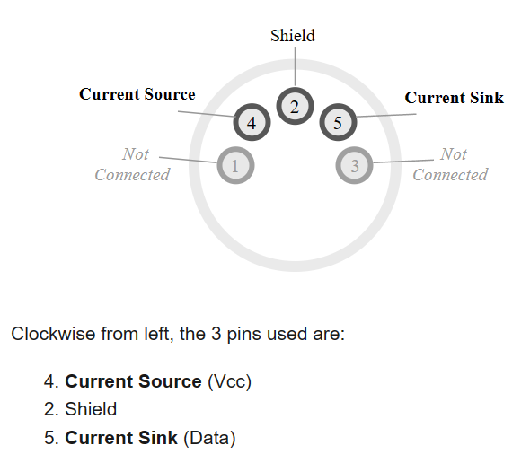
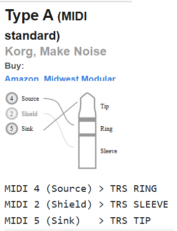
MIDI TRS A
- From minimidi.world
- DIN
- TRS A
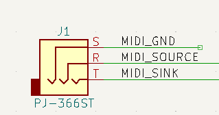
J1 - MIDI In - TRS
J2-J5 - MIDI In - TRS
J6 - Eurorack Power
- 2x8 IDC connector
- Requires 5V power
- Only uses +5V and GND
- Does not use +/-12V, GATE, or CV
J7 - MIDI In - DIN
- Through hole vertical mount DIN connector
- DIN connector stands proud from Front Panel by a small amount
Design
- MIDI In DIN
- MIDI In TRS-A
- MIDI Out TRS-A
Daughtercard
- Daughtercard is 110mm tall
- 9.5mm clearance at top
- 9mm clearance at bottom
Reference Documents
- RP-054 - Specification for use of TRS Connectors with MIDI Devices
- From the page All you need to know about TRS MIDI connections
The SOURCE provides the power, whether 3.3v or 5v, to power an LED in the optocoupler in the receiving device,
while the SINK pulls that power to ground whenever there is data to be transmitted.

DIN MIDI Connector
In the good old DIN5 MIDI Connectors, 3 out of the 5 pins are used. Pin 2 is used as GROUND,
Pin 4 is used as the current SOURCE, while Pin 5 is used as the current SINK.

Type A
The Type A TRS connection is the official standard adopted by the MIDI Association. The Tip is the Sink (pulls the data line down) and the Ring is the Source.
- Deftaudio example
