Difference between revisions of "ER-USB-MIDI"
Jump to navigation
Jump to search
Blwikiadmin (talk | contribs) |
Blwikiadmin (talk | contribs) |
||
| (29 intermediate revisions by the same user not shown) | |||
| Line 1: | Line 1: | ||
| + | [[File:tindie-mediums.png|link=https://www.tindie.com/products/28896/]] | ||
| + | |||
| + | [[FILE:ER-USB-MIDI_P1090014-720PX.jpg]] | ||
| + | |||
== Features == | == Features == | ||
| − | * USB MIDI to MIDI Serial | + | * MIDI/Serial interface |
| − | * | + | ** Out/In |
| + | ** Based on [https://learn.adafruit.com/qt-py-rp2040-usb-to-serial-midi-friends/overview Adafruit QT Py RP2040 USB to Serial MIDI Friends design] | ||
| + | * USB MIDI to MIDI Serial | ||
| + | * MIDI Serial to USB MIDI | ||
* Built on [[ER-PROTO-02]] | * Built on [[ER-PROTO-02]] | ||
* [[QT_Py_(RP2040_based)|XAIO RP2040 CPU]] | * [[QT_Py_(RP2040_based)|XAIO RP2040 CPU]] | ||
| − | + | * MIDI over TRS A type connector | |
| − | * MIDI | + | * J5 = MIDI Serial input |
* J6 = MIDI Serial output | * J6 = MIDI Serial output | ||
| − | |||
| − | === Seeeduino XIAO RP2040 | + | === Resources === |
| + | |||
| + | * [https://minimidi.world/ A simplified guide to TRS MIDI] | ||
| + | |||
| + | == Seeeduino XIAO RP2040 == | ||
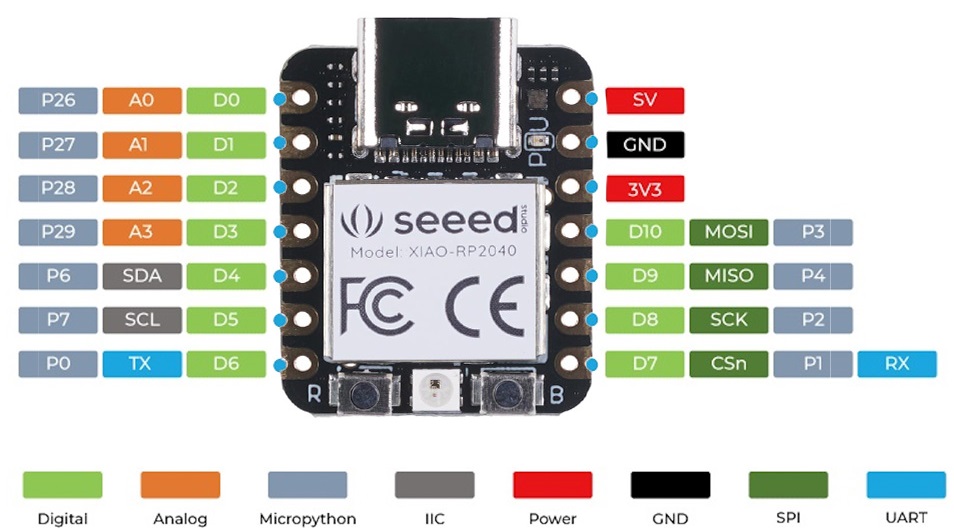
There are 14 GPIO PINs on XIAO RP2040, on which there are 11 digital pins, 4 analog pins, 11 PWM Pins,1 I2C interface, 1 UART interface, 1 SPI interface, 1 SWD Bonding pad interface. | There are 14 GPIO PINs on XIAO RP2040, on which there are 11 digital pins, 4 analog pins, 11 PWM Pins,1 I2C interface, 1 UART interface, 1 SPI interface, 1 SWD Bonding pad interface. | ||
| Line 21: | Line 31: | ||
== Design == | == Design == | ||
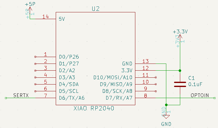
| − | + | === XAIO RP2040 CPU === | |
[[file:ER-USB-MIDI_RP2040.PNG]] | [[file:ER-USB-MIDI_RP2040.PNG]] | ||
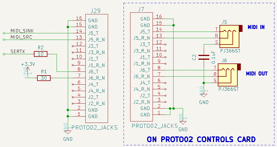
| − | + | === MIDI Jacks === | |
[[file:ER-USB-MIDI_JACKS.PNG]] | [[file:ER-USB-MIDI_JACKS.PNG]] | ||
| − | |||
| − | |||
| − | |||
| − | |||
* J5, J6 = PJ366ST | * J5, J6 = PJ366ST | ||
| Line 38: | Line 44: | ||
** Male Pins on Daughtercard | ** Male Pins on Daughtercard | ||
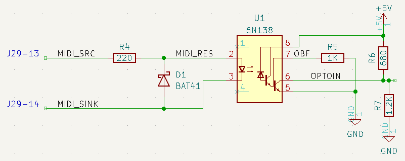
| − | === Daughtercard Prototyping Area | + | === MIDI In === |
| + | |||
| + | * 3.3V MIDI serial out to [[Arduino Pro Mini]] | ||
| + | ** R6 = 680 | ||
| + | ** R7 = 1.2K | ||
| + | |||
| + | [[file:ER-USB-MIDI_IN.PNG]] | ||
| + | |||
| + | == Daughtercard Prototyping Area == | ||
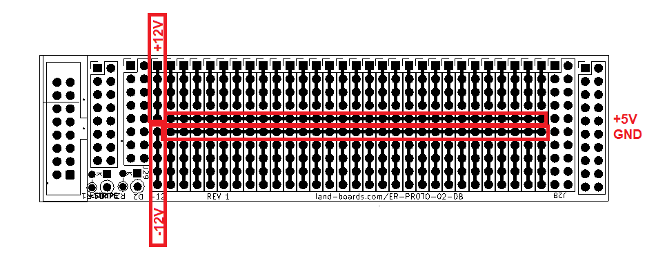
[[FILE:ER-PROTO-02-DB_REAR_PWR.png]] | [[FILE:ER-PROTO-02-DB_REAR_PWR.png]] | ||
| + | |||
| + | == Build == | ||
| + | |||
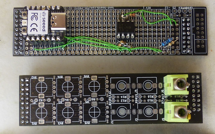
| + | * Daughtercard/Controls card | ||
| + | |||
| + | [[FILE:ER-USB-MIDI_P1090022-720px.jpg]] | ||
| + | |||
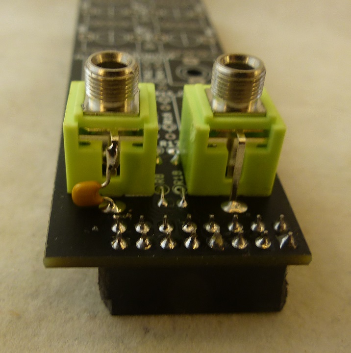
| + | * Cap on MIDI In GND pin | ||
| + | |||
| + | [[FILE:ER-USB-MIDI_P1090027-720px.jpg]] | ||
== Software == | == Software == | ||
| + | * [https://learn.adafruit.com/qt-py-rp2040-usb-to-serial-midi-friends Adafruit MIDI Friends] | ||
| + | ** Bridges USB MIDI to Serial MIDI | ||
| + | *** Takes in MIDI from the USB (typically from a PC running a MIDI player) and send out MIDI | ||
| + | *** Maintains optical isolation on MIDI | ||
| + | * [https://docs.circuitpython.org/projects/midi/en/latest/api.html#adafruit_midi Adafruit MIDI API] | ||
| + | * Listens to MIDI Channel 1 | ||
* Load CircuitPython to card (using v7.x) | * Load CircuitPython to card (using v7.x) | ||
** Press right button then insert USB cable | ** Press right button then insert USB cable | ||
** Drive will appear on PC | ** Drive will appear on PC | ||
** Drop [https://github.com/land-boards/QT-Py/tree/main/CircuitPython/CircuitPython_Firmware/XIAO_RP2040 CircuitPython uf2] onto the drive | ** Drop [https://github.com/land-boards/QT-Py/tree/main/CircuitPython/CircuitPython_Firmware/XIAO_RP2040 CircuitPython uf2] onto the drive | ||
| − | * Drop [https://github.com/land-boards/QT-Py/ | + | * Drop [https://github.com/land-boards/QT-Py/blob/main/CircuitPython/Seeed_XIAO_RP2040/ER-USB-MIDI/code.py application and libraries onto card] - Drop as code.py to auto-run |
| − | * | + | * Download/run [http://www.midieditor.org/ MIDIEditor] |
** Edit | ** Edit | ||
** Settings | ** Settings | ||
** MIDI Output | ** MIDI Output | ||
*** Select CircuitPython Audio | *** Select CircuitPython Audio | ||
| + | ** Load MIDI file ([https://midination.com/midi/free-midi-files/ Free MIDI files sites]) | ||
| + | ** Click play button | ||
Latest revision as of 22:39, 16 January 2023
Contents
Features
- MIDI/Serial interface
- Out/In
- Based on Adafruit QT Py RP2040 USB to Serial MIDI Friends design
- USB MIDI to MIDI Serial
- MIDI Serial to USB MIDI
- Built on ER-PROTO-02
- XAIO RP2040 CPU
- MIDI over TRS A type connector
- J5 = MIDI Serial input
- J6 = MIDI Serial output
Resources
Seeeduino XIAO RP2040
There are 14 GPIO PINs on XIAO RP2040, on which there are 11 digital pins, 4 analog pins, 11 PWM Pins,1 I2C interface, 1 UART interface, 1 SPI interface, 1 SWD Bonding pad interface.
Design
XAIO RP2040 CPU
MIDI Jacks
- J5, J6 = PJ366ST
- Install both Pot/Jack headers/sockets
- Female sockets on Controls card
- Male Pins on Daughtercard
MIDI In
- 3.3V MIDI serial out to Arduino Pro Mini
- R6 = 680
- R7 = 1.2K
Daughtercard Prototyping Area
Build
- Daughtercard/Controls card
- Cap on MIDI In GND pin
Software
- Adafruit MIDI Friends
- Bridges USB MIDI to Serial MIDI
- Takes in MIDI from the USB (typically from a PC running a MIDI player) and send out MIDI
- Maintains optical isolation on MIDI
- Bridges USB MIDI to Serial MIDI
- Adafruit MIDI API
- Listens to MIDI Channel 1
- Load CircuitPython to card (using v7.x)
- Press right button then insert USB cable
- Drive will appear on PC
- Drop CircuitPython uf2 onto the drive
- Drop application and libraries onto card - Drop as code.py to auto-run
- Download/run MIDIEditor
- Edit
- Settings
- MIDI Output
- Select CircuitPython Audio
- Load MIDI file (Free MIDI files sites)
- Click play button


