Difference between revisions of "ER-MOZZI-DB-03"
Jump to navigation
Jump to search
Blwikiadmin (talk | contribs) |
Blwikiadmin (talk | contribs) |
||
| (27 intermediate revisions by the same user not shown) | |||
| Line 1: | Line 1: | ||
| − | [[FILE:ER-PROTO-02- | + | [[FILE:ER-PROTO-02-SET_MOZZI_FRONT-3D_V3.png]] |
== Features == | == Features == | ||
| + | * Eurorack card optimized to use with [https://sensorium.github.io/Mozzi/ MOZZI Arduino library] | ||
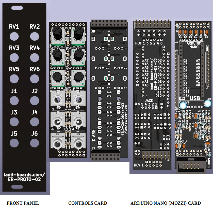
* Daughtercard to [[ER-PROTO-02]] card | * Daughtercard to [[ER-PROTO-02]] card | ||
** Uses Front Panel and Controls card | ** Uses Front Panel and Controls card | ||
| Line 9: | Line 10: | ||
**** Up to 5 in/out jacks | **** Up to 5 in/out jacks | ||
**** High Def Sound output jack | **** High Def Sound output jack | ||
| − | * Arduino | + | * Any jack/pot can be "jumpered" to any Arduino pin |
| + | * [[Arduino Nano]] | ||
| + | ** ATMega328 CPU Comparable with Arduino UNO | ||
| + | ** 5V, 16 MHz | ||
| + | ** USB interface, on USB Mini | ||
| + | ** Installs onto female header/removable | ||
| + | ** DC regulator | ||
| + | ** Reset pushbutton | ||
| + | * +12V operation | ||
| + | * 108.5mmx28mm card | ||
=== Arduino Pins === | === Arduino Pins === | ||
| Line 15: | Line 25: | ||
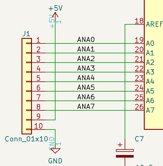
* The Arduino NANO has 8 Analog Inputs (0-7) | * The Arduino NANO has 8 Analog Inputs (0-7) | ||
* The Arduino NANO has 11 Digital I/O pins (2-13) | * The Arduino NANO has 11 Digital I/O pins (2-13) | ||
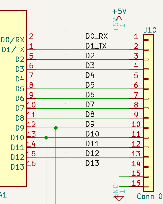
| + | ** D0, D1 are used for the Serial port | ||
* The [[ER-PROTO-02]] controls card has 6 pots (RV1-RV6) and 6 jacks (J1-J6) | * The [[ER-PROTO-02]] controls card has 6 pots (RV1-RV6) and 6 jacks (J1-J6) | ||
| − | ** 6 Pots are brought into | + | ** 6 Pots are brought into this card |
| − | ** 6 Jacks are brought into | + | ** 6 Jacks are brought into this card |
*** J1-J5 Jacks can be used for analog inputs, digital inputs or digital outputs | *** J1-J5 Jacks can be used for analog inputs, digital inputs or digital outputs | ||
*** J6 Jack is a dedicated output (J6) connected to Hi Def output Arduino pins D9, D10 | *** J6 Jack is a dedicated output (J6) connected to Hi Def output Arduino pins D9, D10 | ||
| + | * Any jack/pot can be "jumpered" to any Arduino pin | ||
| − | + | == Jacks Pin Protection Circuit == | |
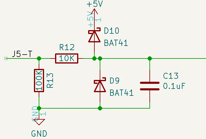
* Example circuit configured as input | * Example circuit configured as input | ||
| Line 105: | Line 117: | ||
=== J2 - Jacks Pins === | === J2 - Jacks Pins === | ||
| + | |||
| + | * Use right angle header if using BERG jumpers | ||
[[FILE:ER-MOZZI-DB-03_J2.PNG]] | [[FILE:ER-MOZZI-DB-03_J2.PNG]] | ||
| Line 125: | Line 139: | ||
[[FILE:ER-MOZZI-DB-03_J10.PNG]] | [[FILE:ER-MOZZI-DB-03_J10.PNG]] | ||
| + | |||
| + | == Controls Card Pots/Jacks == | ||
| + | |||
| + | * Up to 6 pots | ||
| + | * Up to 6 jacks | ||
| + | |||
| + | === Pots on Controls card === | ||
| + | |||
| + | [[file:ER-PROTO-02_CTRLS_POT.PNG]] | ||
| + | |||
| + | * Jumpers to pull up/down ends of pots | ||
| + | * Typical 100K pot | ||
| + | * Typical 1K series resistor on pot wiper | ||
| + | |||
| + | === Jacks on Controls card === | ||
| + | |||
| + | [[file:ER-PROTO-02_CTRLS_JACK.PNG]] | ||
| + | |||
| + | * Tip has series resistor | ||
| + | * Ring/Tip switch | ||
| + | ** PJ-398 has tip switch | ||
| + | ** PJ-366ST has stereo ring connection | ||
| + | *** Ring has series resistor | ||
== Software / Example Projects == | == Software / Example Projects == | ||
| Line 142: | Line 179: | ||
=== HAGIWO MOZZI builds === | === HAGIWO MOZZI builds === | ||
| − | |||
| − | |||
* [https://note.com/solder_state HAGIWO builds] | * [https://note.com/solder_state HAGIWO builds] | ||
Latest revision as of 18:45, 11 March 2023
Contents
Features
- Eurorack card optimized to use with MOZZI Arduino library
- Daughtercard to ER-PROTO-02 card
- Uses Front Panel and Controls card
- Controls card populated as required
- Up to 6 Pots
- Up to 5 in/out jacks
- High Def Sound output jack
- Controls card populated as required
- Uses Front Panel and Controls card
- Any jack/pot can be "jumpered" to any Arduino pin
- Arduino Nano
- ATMega328 CPU Comparable with Arduino UNO
- 5V, 16 MHz
- USB interface, on USB Mini
- Installs onto female header/removable
- DC regulator
- Reset pushbutton
- +12V operation
- 108.5mmx28mm card
Arduino Pins
- The Arduino NANO has 8 Analog Inputs (0-7)
- The Arduino NANO has 11 Digital I/O pins (2-13)
- D0, D1 are used for the Serial port
- The ER-PROTO-02 controls card has 6 pots (RV1-RV6) and 6 jacks (J1-J6)
- 6 Pots are brought into this card
- 6 Jacks are brought into this card
- J1-J5 Jacks can be used for analog inputs, digital inputs or digital outputs
- J6 Jack is a dedicated output (J6) connected to Hi Def output Arduino pins D9, D10
- Any jack/pot can be "jumpered" to any Arduino pin
Jacks Pin Protection Circuit
- Example circuit configured as input
- Same circuit on all 5 J1-J5 jacks
- Configured as input
- I/O Protection
- Diode Clamps
- Series resistor (R12 in example)
- Works along with diode clamps
- 10K Typical value
- Parallel resistor (R13 in example)
- 100K typical value
- Lightly pulls input to ground when no jack is connected
- Parallel capacitor (C13 in example)
- 10nF or 0.1uF are typical values
- Smooths analog input (noise reduction)
- 0 Ohm Series resistor on Controls card for 5V inputs
- Goes to jack tip pin
- I/O Protection
- Configured as output
- I/O Protection - Diode Clamps
- 0 Ohm Series resistor (R12 in example)
- DNP (Do Not Populate) Parallel resistor (R13 in example)
- DNP Parallel capacitor (C13 in example)
- Typical 470 or 1K Ohm Series resistor on Controls card
- Goes to jack tip pin
- Works along with diode clamps
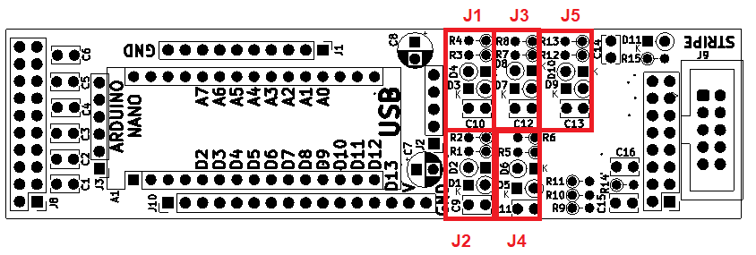
Jacks Pin Protection Circuit Reference Designator cross reference table
- Location of input circuitry on cards
| JACK | R SERIES | R PARALLEL | C PARALLEL | DIODES |
|---|---|---|---|---|
| J1 | R3 | R4 | C10 | D3/D4 |
| J2 | R1 | R2 | C9 | D1/D2 |
| J3 | R7 | R8 | C12 | D7/D8 |
| J4 | R5 | R6 | C11 | D5/D6 |
| J5 | R12 | R13 | C13 | D9/D10 |
Jacks/Headers
J1 - Arduino Analog Pins
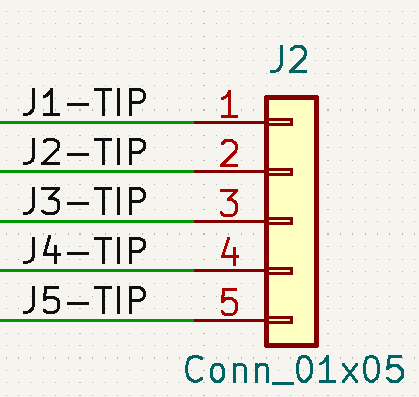
J2 - Jacks Pins
- Use right angle header if using BERG jumpers
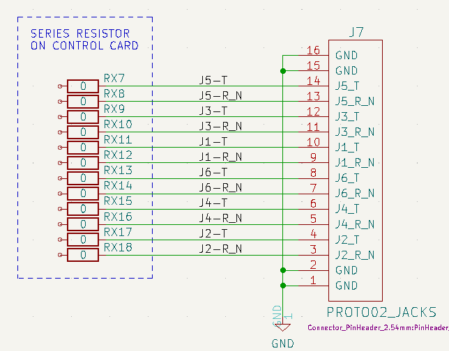
J7 - Jacks connections to Controls card
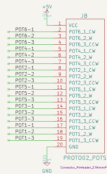
J8 - Pots connections to Controls card
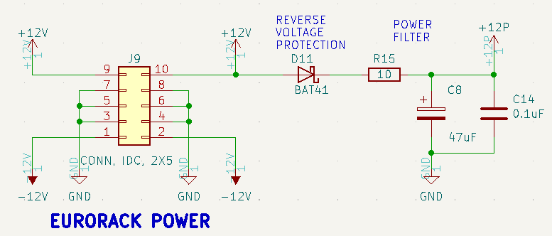
J9 - Eurorack Power
- Power filter
J10 - Arduino Digital Pins
Controls Card Pots/Jacks
- Up to 6 pots
- Up to 6 jacks
Pots on Controls card
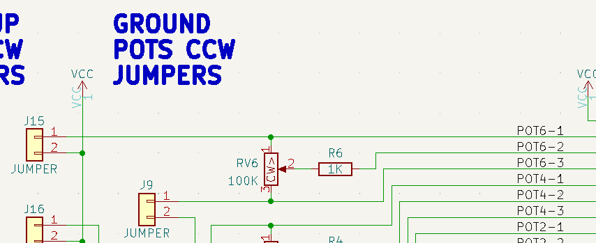
- Jumpers to pull up/down ends of pots
- Typical 100K pot
- Typical 1K series resistor on pot wiper
Jacks on Controls card
- Tip has series resistor
- Ring/Tip switch
- PJ-398 has tip switch
- PJ-366ST has stereo ring connection
- Ring has series resistor
Software / Example Projects
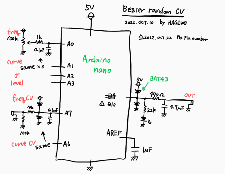
- HAGIWO Bezier curve random CV generator
- HAGIWO Envelope Generator Module
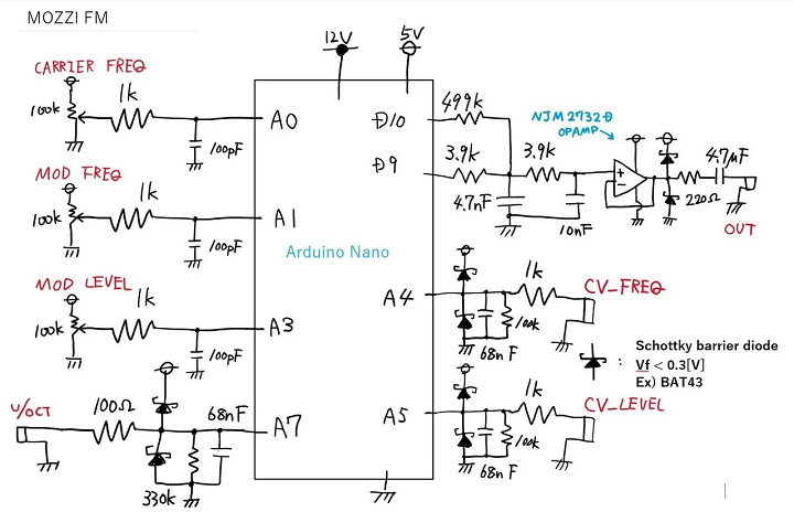
- HAGIWO FM VCO Module
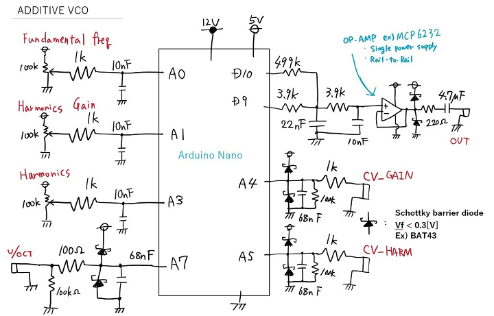
- HAGIWO Additive VCO (harmonic addition VCO)
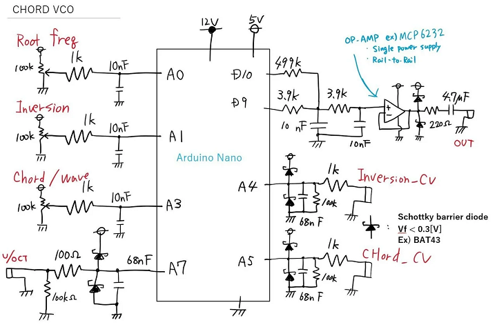
- HAGIWO CHORD VCO with mozzi library
- Using Mozzi Library With 5 Potentiometers
- Atari Punk Synth V2
- Arduino Multi-pot Mozzi FM Synthesis
- Arduino mozzi FM VCO Module for 650 yen - Modular synth self-made
- Nuts and Volts AUDUINO Synth build for the Arduino NANO
- MozMo = ATMega328 plus FTDI
HAGIWO MOZZI builds
- HAGIWO builds
- Pots
- Install RV1-RV4 = 100K
- Install series resistor R1-R3 1K
- Install Pull-up/Pull-down jumpers
- Jacks
- J3-J5 = PJ398SM
- J6 = PJ366ST
Additive VCO
- 3 pots (Fundamental Frequency, Harmonics Gain, Harmonic)
- 3 CV input jacks (V/Oct, Gain, Harmonic)
- 1 PWM output jack
- Output swings 1V-4V
- Additive VCO Code
Chord VCO
- 3 pots (Root Frequency, Inversion, Chord/Wave)
- 3 CV input jacks (V/Oct, Inversion, Chord/Wave)
- 1 PWM output jack
- Output swings 2.5V +/- 100mV
- CHORD VCO Code
FM VCO
- 3 pots (Carrier Frequency, Mod Freq, Mod Level)
- 3 CV input jacks (V/Oct, Mod Freq, Mod Level)
- 1 PWM output jack
- Output swings 0-5V
- FM VCO Code
Triple Mode VCO
- FM, Additive, Chord modes
- Started from Testbld Code base
- Replaced mode select switch with RV4 mode select pot
- RV4 is on Analog 3
- Add RV4 = 100K to controls card
- Add R4 = 1K to controls card
- Add C2 = 0.1uF to controls card
- Add R4 = 0 ohms jumper to daughtercard
- Replaced mode select switch with RV4 mode select pot
- PWM output
- Output swings 2V-3V
