Difference between revisions of "TinyGrid85"
Jump to navigation
Jump to search
Blwikiadmin (talk | contribs) |
Blwikiadmin (talk | contribs) |
||
| (4 intermediate revisions by the same user not shown) | |||
| Line 8: | Line 8: | ||
* Arduino Compatible (works with Arduino bootloader and Arduino IDE) | * Arduino Compatible (works with Arduino bootloader and Arduino IDE) | ||
* Prototyping area with power/ground connections | * Prototyping area with power/ground connections | ||
| − | * Brings out all 5 I/O and reset lines to grid columns | + | ** Brings out all 5 I/O and reset lines to grid columns |
| − | * Laid out like a breadboard with vertically connected traces. | + | ** Laid out like a breadboard with vertically connected traces. |
| − | * Power and Ground horizontal connections though all columns | + | ** Power and Ground horizontal connections though all columns |
| − | * Labeled (with letters/numbers) for easy documentation | + | ** Labeled (with letters/numbers) for easy documentation |
* H1 - Install jumper to select regulator or remove for ISP +5V | * H1 - Install jumper to select regulator or remove for ISP +5V | ||
* H2 - 6-pin ISP Download Header | * H2 - 6-pin ISP Download Header | ||
| Line 30: | Line 30: | ||
[[File:Tiny85-ISP-Conn.PNG]] | [[File:Tiny85-ISP-Conn.PNG]] | ||
| − | + | [[File:ATtiny45-85.png]] | |
| − | [[ | + | == Programming == |
| + | |||
| + | * [https://www.arduino.cc/en/Tutorial/ArduinoISP#toc3 Program using an Arduino UNO running ArduinoISP]. | ||
| + | * [https://create.arduino.cc/projecthub/arjun/programming-attiny85-with-arduino-uno-afb829 Program ATTiny using an Arduino UNO] | ||
| + | * Need to program bootloader | ||
== Assembly Sheet == | == Assembly Sheet == | ||
* [[TinyGrid85 Assembly Sheet]] | * [[TinyGrid85 Assembly Sheet]] | ||
Latest revision as of 15:25, 4 May 2022
Contents
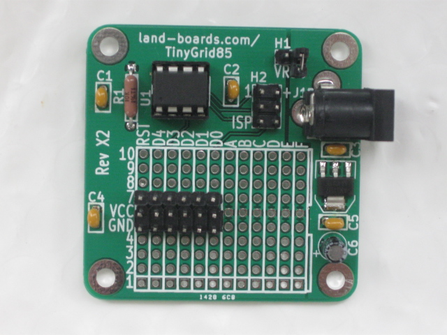
Features
- ATMEL ATTiny85 Microprocessor (or compatible 8-pin part)
- Arduino Compatible (works with Arduino bootloader and Arduino IDE)
- Prototyping area with power/ground connections
- Brings out all 5 I/O and reset lines to grid columns
- Laid out like a breadboard with vertically connected traces.
- Power and Ground horizontal connections though all columns
- Labeled (with letters/numbers) for easy documentation
- H1 - Install jumper to select regulator or remove for ISP +5V
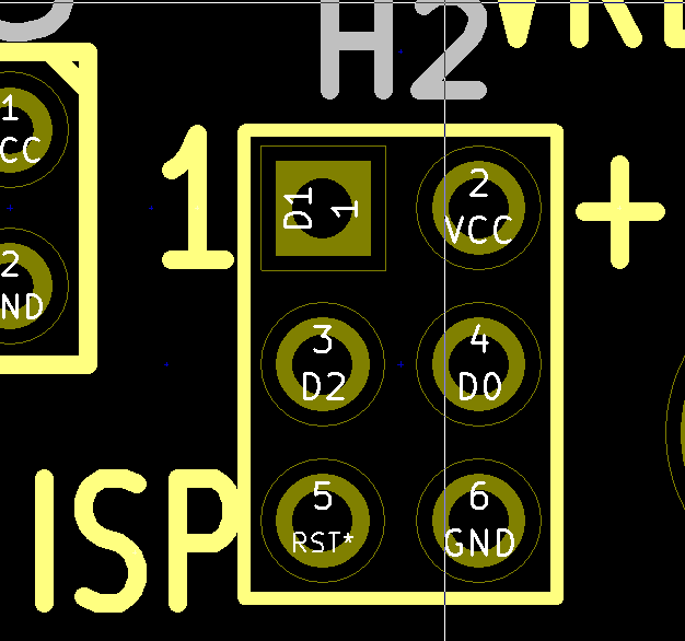
- H2 - 6-pin ISP Download Header
- 5V Power Regulator with generous area under the regulator for heat dissipation
- 2.1mm Connector for AC/DC adapter 7-9V input
- (4) 4-40 or M3 screw holes for solid mounting
- 49x49 mm board
Connectors
H1 - VREG Jumper
- Install to power board from the on-board regulator
- Remove when connecting powered ISP cable
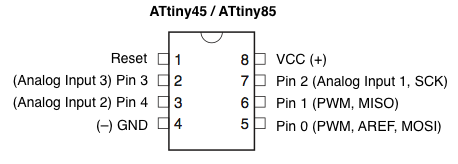
H2 - ISP Connector
Programming
- Program using an Arduino UNO running ArduinoISP.
- Program ATTiny using an Arduino UNO
- Need to program bootloader


