Difference between revisions of "FTDI-49MM"
Jump to navigation
Jump to search
Blwikiadmin (talk | contribs) |
Blwikiadmin (talk | contribs) |
||
| (32 intermediate revisions by the same user not shown) | |||
| Line 1: | Line 1: | ||
| + | [[File:tindie-mediums.png|link=https://www.tindie.com/products/land_boards/ftdi-card-with-extra-features/]] | ||
| + | |||
[[File:FTDI-P1746-CROPPED-720PX.jpg]] | [[File:FTDI-P1746-CROPPED-720PX.jpg]] | ||
== Features == | == Features == | ||
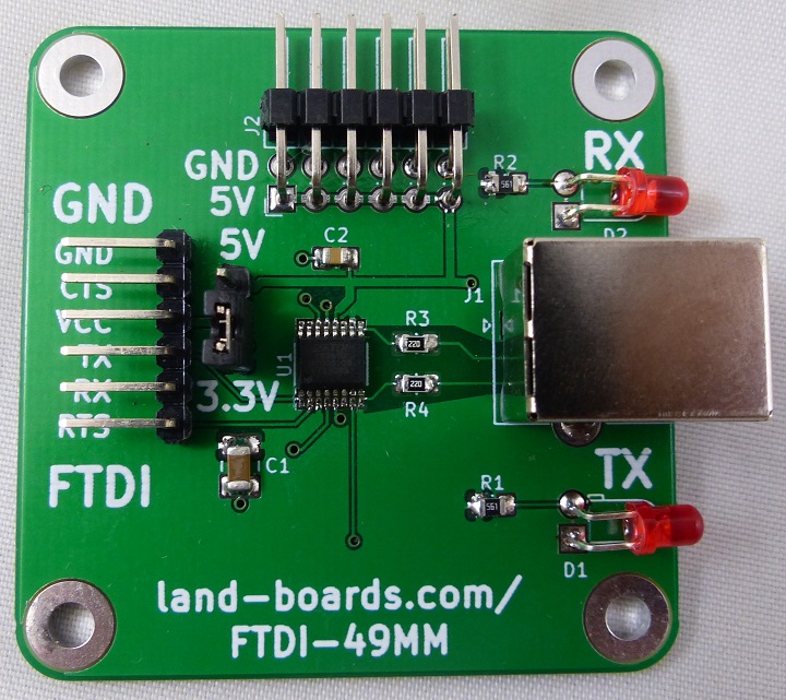
| − | * FTDI | + | * [https://www.ftdichip.com/Products/ICs/FT230X.html FT230X] USB-to-FTDI Serial IC |
* USB B connector (not micro or mini, but the beefy USB B connector) | * USB B connector (not micro or mini, but the beefy USB B connector) | ||
* FTDI compatible pinout | * FTDI compatible pinout | ||
* 3.3V or 5V selection jumper | * 3.3V or 5V selection jumper | ||
| − | * Header for 5V power distribution | + | * Inputs are 5V tolerant (when set to 3.3V levels) |
| + | * 2x6 Header for 5V power distribution | ||
| + | * Rx and Tx LEDs | ||
* (4) 4-40 mounting holes | * (4) 4-40 mounting holes | ||
| − | ** Mounts to 95mm to 45mm adapter | + | ** Mounts to [[CARRIER95TO49MM|optional 95mm to 45mm adapter]] |
** Stacks up with standoffs for use with other 95mm cards | ** Stacks up with standoffs for use with other 95mm cards | ||
| + | * Can be direct wired to [[DTE]] or [[DCE]] TTL-to-RS-232 converters | ||
| + | |||
| + | == Headers/Jumpers/Connectors == | ||
| + | |||
| + | === 5V/3.3V Jumper === | ||
| + | |||
| + | * Select 5V or 3.3V signal levels on FTDI connector | ||
| + | * On FTDI connector VCC pin pin 3 | ||
| + | (Inputs are 5V tolerant (when set to 3.3V levels) | ||
| + | |||
| + | === FTDI Connector === | ||
| + | |||
| + | * Right angle 1x6 pins | ||
| + | |||
| + | # GND | ||
| + | # CTSn (IN) | ||
| + | # VCC | ||
| + | # TX (OUT) | ||
| + | # RX (IN) | ||
| + | # RTSn (OUT) | ||
| + | |||
| + | === USB Connector === | ||
| + | |||
| + | * USB B Connector | ||
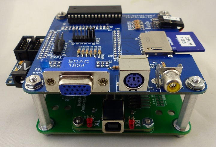
== Stackup with EP2 FPGA card == | == Stackup with EP2 FPGA card == | ||
| + | |||
| + | * Top to bottom of stackup | ||
| + | # [[EP2C5-DB]] | ||
| + | # [[Cyclone_II_EP2C5_Mini_Dev_Board]] Card | ||
| + | # FTDI-49MM - (this card) | ||
| + | # [[CARRIER95TO49MM]] | ||
[[File:P1752-CROPPED-720PX.jpg]] | [[File:P1752-CROPPED-720PX.jpg]] | ||
| − | == | + | == Card Test == |
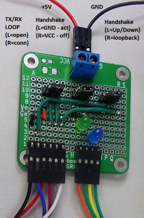
| − | # | + | [[File:OPTOUSB_Tester_Card-Annotated-720pxV.jpg]] |
| − | + | ||
| − | + | * UUT card | |
| − | + | * Connect [[OPTOUSB#Card_Test|OPTOUSB tester card]] to UUT | |
| − | + | ** Connect FTDI - black = ground | |
| − | + | ** Does not require LEDs connections | |
| + | ** Does not require 5V Power Supply (used for [[OPTOUSB]] card) | ||
| + | * Plug in USB to computer | ||
| + | ** Should hear Windoze detect sound | ||
| + | ** Use Device Manager to determine which COM port is used | ||
| + | * Run puTTY | ||
| + | ** Baud rate = 115,200 baud | ||
| + | ** Hardware handshake RTS/CTS | ||
| + | ** COM port from Device Manager | ||
| + | * Jumper Settings - Normal operation | ||
| + | ** Left jumper in right position (loopback data) | ||
| + | ** Middle jumper in left position (handshake = active/ground) | ||
| + | ** Right jumper in right position (loopback handshake) | ||
| + | ** Type on keyboard and verify it returns data | ||
| + | ** Verify both LEDs on the UUT light | ||
| + | * Jumper settings - Test Tx/Rx isolation | ||
| + | ** Move left jumper to left position | ||
| + | ** Type data nothing should come back | ||
| + | ** Verify RX LED on the UUT only lights | ||
| + | ** Move left jumper to right position | ||
| + | * Jumper settings - Test RTS/CTS | ||
| + | ** Move right jumper to left position (handshake controlled by middle jumper) | ||
| + | ** Type and characters should return | ||
| + | ** Move middle jumper to to right position (hardware handshake off) | ||
| + | ** Type and nothing should go through | ||
| + | ** Move middle jumper to to left position (hardware handshake on) | ||
| + | ** Characters that were buffered should come in at once | ||
| + | * Mark test coupon on rear of card | ||
== Assembly Sheet == | == Assembly Sheet == | ||
[[FTDI-49MM Assembly Sheet]] | [[FTDI-49MM Assembly Sheet]] | ||
Latest revision as of 19:58, 16 October 2021
Contents
Features
- FT230X USB-to-FTDI Serial IC
- USB B connector (not micro or mini, but the beefy USB B connector)
- FTDI compatible pinout
- 3.3V or 5V selection jumper
- Inputs are 5V tolerant (when set to 3.3V levels)
- 2x6 Header for 5V power distribution
- Rx and Tx LEDs
- (4) 4-40 mounting holes
- Mounts to optional 95mm to 45mm adapter
- Stacks up with standoffs for use with other 95mm cards
- Can be direct wired to DTE or DCE TTL-to-RS-232 converters
Headers/Jumpers/Connectors
5V/3.3V Jumper
- Select 5V or 3.3V signal levels on FTDI connector
- On FTDI connector VCC pin pin 3
(Inputs are 5V tolerant (when set to 3.3V levels)
FTDI Connector
- Right angle 1x6 pins
- GND
- CTSn (IN)
- VCC
- TX (OUT)
- RX (IN)
- RTSn (OUT)
USB Connector
- USB B Connector
Stackup with EP2 FPGA card
- Top to bottom of stackup
- EP2C5-DB
- Cyclone_II_EP2C5_Mini_Dev_Board Card
- FTDI-49MM - (this card)
- CARRIER95TO49MM
Card Test
- UUT card
- Connect OPTOUSB tester card to UUT
- Connect FTDI - black = ground
- Does not require LEDs connections
- Does not require 5V Power Supply (used for OPTOUSB card)
- Plug in USB to computer
- Should hear Windoze detect sound
- Use Device Manager to determine which COM port is used
- Run puTTY
- Baud rate = 115,200 baud
- Hardware handshake RTS/CTS
- COM port from Device Manager
- Jumper Settings - Normal operation
- Left jumper in right position (loopback data)
- Middle jumper in left position (handshake = active/ground)
- Right jumper in right position (loopback handshake)
- Type on keyboard and verify it returns data
- Verify both LEDs on the UUT light
- Jumper settings - Test Tx/Rx isolation
- Move left jumper to left position
- Type data nothing should come back
- Verify RX LED on the UUT only lights
- Move left jumper to right position
- Jumper settings - Test RTS/CTS
- Move right jumper to left position (handshake controlled by middle jumper)
- Type and characters should return
- Move middle jumper to to right position (hardware handshake off)
- Type and nothing should go through
- Move middle jumper to to left position (hardware handshake on)
- Characters that were buffered should come in at once
- Mark test coupon on rear of card


