Difference between revisions of "HW-9 VFO"
Jump to navigation
Jump to search
Blwikiadmin (talk | contribs) |
Blwikiadmin (talk | contribs) |
||
| (13 intermediate revisions by the same user not shown) | |||
| Line 65: | Line 65: | ||
=== 128x32 OLED === | === 128x32 OLED === | ||
| + | |||
| + | [[File:Si5351_003_720px.jpg]] | ||
* [https://www.ebay.com/itm/2pcs-0-91-128x32-IIC-I2C-White-OLED-LCD-Display-DIY-Module-For-Arduino/293688288048?ssPageName=STRK%3AMEBIDX%3AIT&_trksid=p2057872.m2749.l2649 Ebay] | * [https://www.ebay.com/itm/2pcs-0-91-128x32-IIC-I2C-White-OLED-LCD-Display-DIY-Module-For-Arduino/293688288048?ssPageName=STRK%3AMEBIDX%3AIT&_trksid=p2057872.m2749.l2649 Ebay] | ||
| Line 104: | Line 106: | ||
[[File:RotaryEncoderCAD.PNG]] | [[File:RotaryEncoderCAD.PNG]] | ||
| + | |||
| + | |||
| + | [[File:Si5351_004_720px.jpg]] | ||
* Includes pushbutton Switch | * Includes pushbutton Switch | ||
| Line 112: | Line 117: | ||
* [http://www.mathertel.de/Arduino/RotaryEncoderLibrary.aspx Library for the Arduino environment for using a rotary encoder as an input] | * [http://www.mathertel.de/Arduino/RotaryEncoderLibrary.aspx Library for the Arduino environment for using a rotary encoder as an input] | ||
| − | === Si5351 | + | === Si5351 Frequency Generator === |
| + | |||
| + | [[File:Si5351_001_720px.jpg]] | ||
[[File:VFO3.PNG]] | [[File:VFO3.PNG]] | ||
| + | * I2C Daisy-chain connector | ||
* 3 outputs | * 3 outputs | ||
** Tx | ** Tx | ||
** Rx (may not need to use separate output) | ** Rx (may not need to use separate output) | ||
** BFO - could be adjusted | ** BFO - could be adjusted | ||
| + | |||
| + | [[File:Si5351_002_720px.jpg]] | ||
| + | |||
| + | ==== Measurements ==== | ||
==== VFO TX ==== | ==== VFO TX ==== | ||
| Line 171: | Line 183: | ||
[[File:BFO_Filter_IL.PNG]] | [[File:BFO_Filter_IL.PNG]] | ||
| − | == Libraries == | + | == Libraries/Example Code == |
| − | + | * [https://github.com/land-boards/lb-Arduino-Code/tree/master/STM32/VFO_Si5351 Land Boards Application] | |
* [https://github.com/pu2clr/VFO_BFO_OLED_ARDUINO VFO and BFO with Si5351A, OLED and Arduino] | * [https://github.com/pu2clr/VFO_BFO_OLED_ARDUINO VFO and BFO with Si5351A, OLED and Arduino] | ||
* [https://github.com/olikraus/u8g2 U8g2: Library for monochrome displays, version 2] | * [https://github.com/olikraus/u8g2 U8g2: Library for monochrome displays, version 2] | ||
| Line 183: | Line 195: | ||
== Videos == | == Videos == | ||
| + | |||
| + | === VFO Design === | ||
<video type="youtube">58G5atwBX2M</video> | <video type="youtube">58G5atwBX2M</video> | ||
| Line 195: | Line 209: | ||
* [https://www.youtube.com/c/CharlieMorrisZL2CTM/videos Charlie Morris YouTube channel] | * [https://www.youtube.com/c/CharlieMorrisZL2CTM/videos Charlie Morris YouTube channel] | ||
| + | |||
| + | === Misc videos === | ||
| + | |||
| + | <video type="youtube">rPM1vvGorTo</video> | ||
| + | |||
| + | === Mods === | ||
| + | |||
| + | <video type="youtube">rABYJi0vm7g</video> | ||
| + | |||
| + | * 4 Led's in the HW-9 taking only 5 MA when wired in series with a 2200 ohm 1/4 watt resistor. | ||
| + | * A total of 20 MA to light the dial and meter. | ||
| + | * The space between the front panel and the chassis here is very small so the tiny LED's are required to do the job . | ||
Latest revision as of 10:38, 30 October 2020
This is a work in process - Gathering pieces.
Features
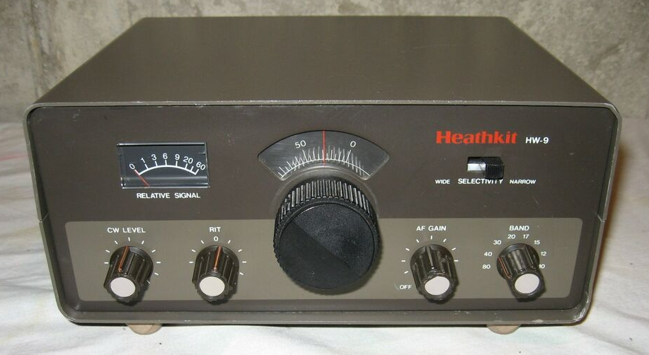
Replace HW-9 internal VFO with a digital VFO
- HW-9 VFO has legendary issues
- Mechanical issues with vernier
- Drift due to thermal
- Lack of resolution
- Backwards dial
- Fits within HW-9 VFO Box
- Controls Tx/Rx/BFO frequencies with rotary encoder
- 10 Hz steps
- DD1306 OLED Display
- I2C Interface
- "Curved" display
- Uses RIT control on HW-9
- +/- 1 KHz RIT
- Blue Pill Microprocessor
- Arduino compatible
- 3.3V
- Understands band switch for MHz displayed
- Si5351 Oscillator
- I2C Interface
- 3 Outputs
- Transmit frequency
- Receiver frequency include offset plus RIT
- BFO frequency
- Low pass filters to turn square waves to sine waves
- 27 MHz crystal
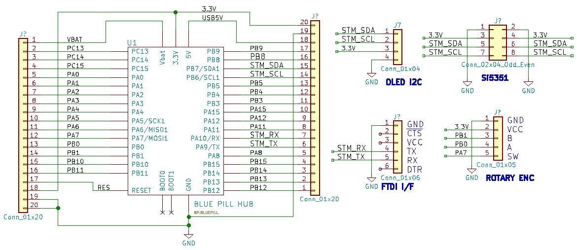
Schematic
Connections to Radio
- RIT pot
- Connects to Analog input
- Polled occasionally while in receive
- Connects to Analog input
- Band switch
- SW1 9V
- T/R - transmit/receive
Parts
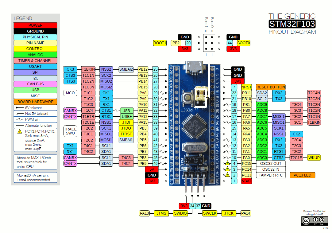
Blue Pill Card
- 3.3V operation work without level shifters for I2C
- OLED can run from 3.3V
- Si5351 can only run from 3.3V
- Used right angle headers and Dupont cables
- Replaced BOOT 0,1 jumpers
- Jumper on BOOT1
- Switch on BOOT0 - easier to download code
- Download via serial
- Arduino IDE
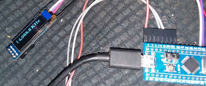
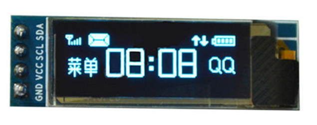
128x32 OLED
Arduino Library for OLED
U8G2_SSD1306_128X32_UNIVISION_F_HW_I2C u8g2(U8G2_R0, /* reset=*/ U8X8_PIN_NONE); // STM32, Ebay OLED
u8g2.setFont(u8g2_font_ncenB14_tr);
Hello World Code
U8G2_SSD1306_128X32_UNIVISION_F_HW_I2C u8g2(U8G2_R0, /* reset=*/ U8X8_PIN_NONE);   // STM32, Ebay OLED

void setup(void) {
  u8g2.begin();
}

void loop(void) {
  u8g2.clearBuffer();			// clear the internal memory
  u8g2.setFont(u8g2_font_ncenB08_tr);	// choose a suitable font
  u8g2.drawStr(0,10,"Hello World!");	// write something to the internal memory
  u8g2.sendBuffer();			// transfer internal memory to the display
  delay(1000);
}
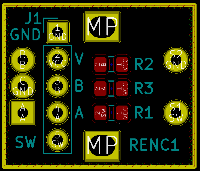
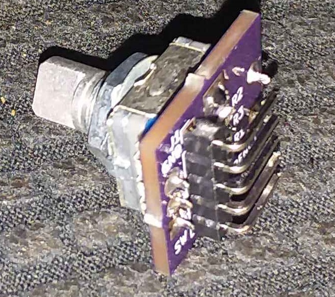
Rotary Encoder/Breakout Board
- Includes pushbutton Switch
- Includes Pull-Up resistors
- Needs R/C filter on output for debounce
- Reading Rotary Encoders - Arduino reference
- Simple Rotary Encoder Arduino library
- Library for the Arduino environment for using a rotary encoder as an input
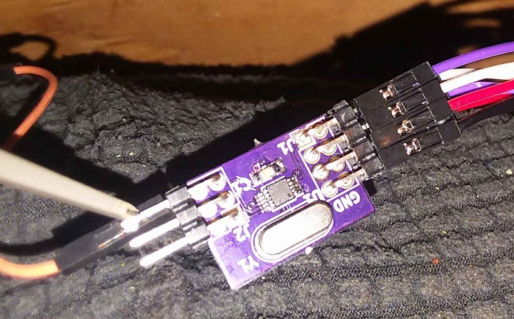
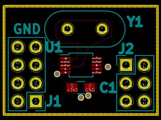
Si5351 Frequency Generator
- I2C Daisy-chain connector
- 3 outputs
- Tx
- Rx (may not need to use separate output)
- BFO - could be adjusted
Measurements
VFO TX
- 250 KHz range
- From 5.9993-5.7493 MHz
VFO RX
- RIT knob is taken in through an A/D and adjusts the receive frequency plus/minus 1 KHz
BFO
- 8.8314 MHz in receive
- 8.8307 MHz in transmit
- 700 Hz difference but could be adjusted
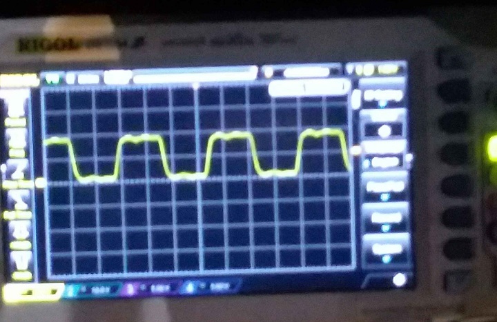
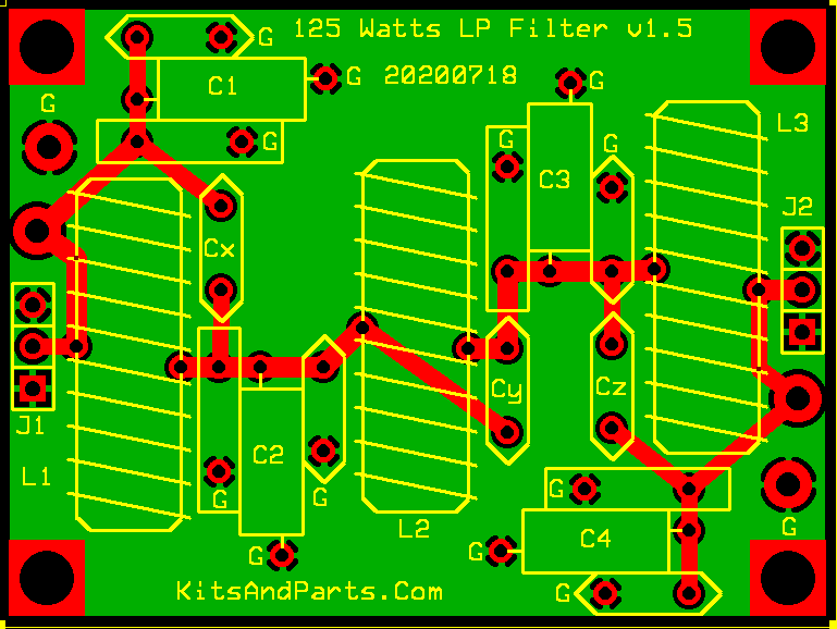
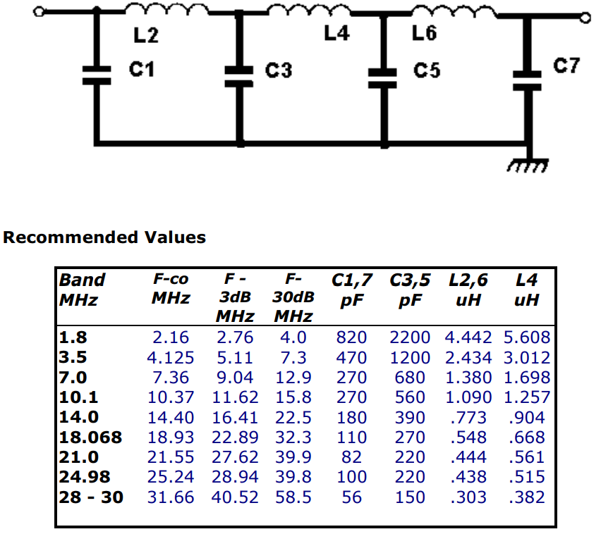
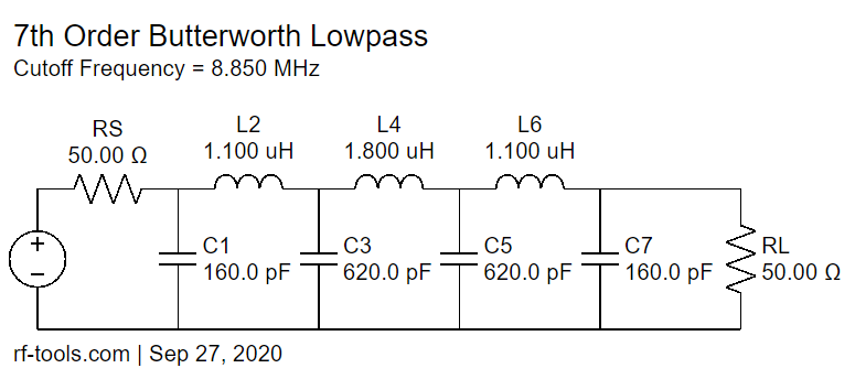
Low Pass Filters
- Si5351 has square wave outputs
- LP filter can be used to change squarewave into sinewave
- LC Filters Design Tool - calculator
- Kits and Parts dot Com
- Build a 7-pole Universal Low Pass Filter for HF
- Butterworth
- Replace with SMT card?
- VFO and BFO frequencies are outside the bands (deliberately to void collisions)
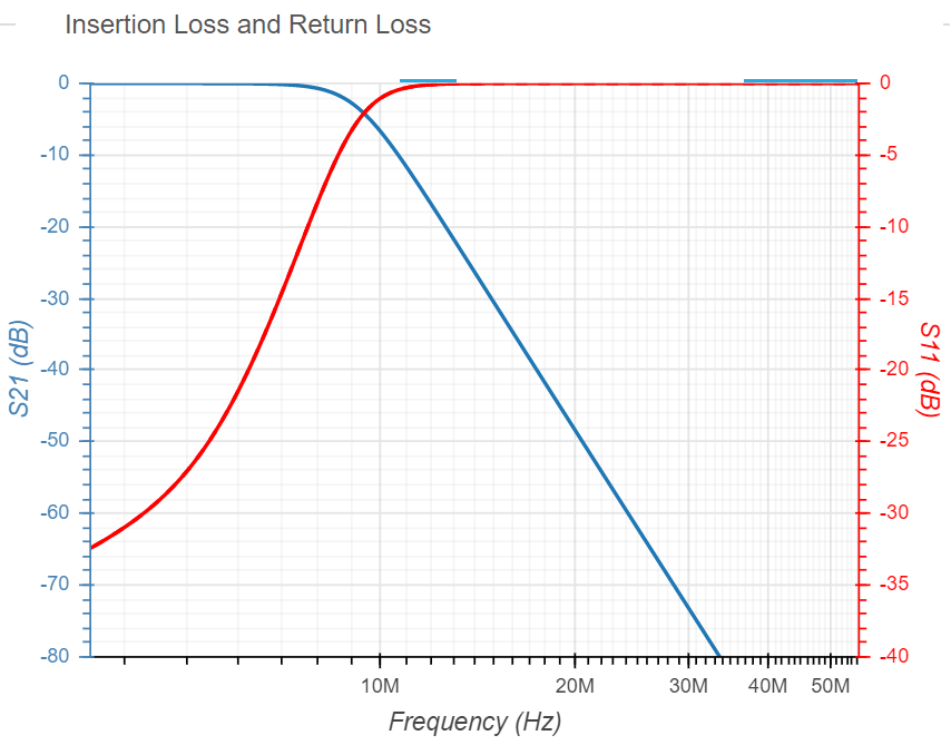
BFO Filter
- 8.8314 MHz in receive
- 8.8307 MHz in transmit
Libraries/Example Code
- Land Boards Application
- VFO and BFO with Si5351A, OLED and Arduino
- U8g2: Library for monochrome displays, version 2
- Si5351 Library for Arduino
- Universal Digital VFO Si570/Si5351
- Adafruit_Si5351
- Si5351 Library for avr-gcc
- vk3hn_VFO_controller
- Simple BFO with si5351 controlled by Arduino
Videos
VFO Design
Misc videos
Mods
- 4 Led's in the HW-9 taking only 5 MA when wired in series with a 2200 ohm 1/4 watt resistor.
- A total of 20 MA to light the dial and meter.
- The space between the front panel and the chassis here is very small so the tiny LED's are required to do the job .
