Difference between revisions of "RF-Amp"
Jump to navigation
Jump to search
Blwikiadmin (talk | contribs) |
Blwikiadmin (talk | contribs) |
||
| Line 6: | Line 6: | ||
* +22 dB gain | * +22 dB gain | ||
* [http://toroids.info/FT37-43.php FT37-43] toroids | * [http://toroids.info/FT37-43.php FT37-43] toroids | ||
| − | |||
** Wideband Transformers 5 - 400 MHz | ** Wideband Transformers 5 - 400 MHz | ||
** Power Transformers 0.5 - 30 MHz | ** Power Transformers 0.5 - 30 MHz | ||
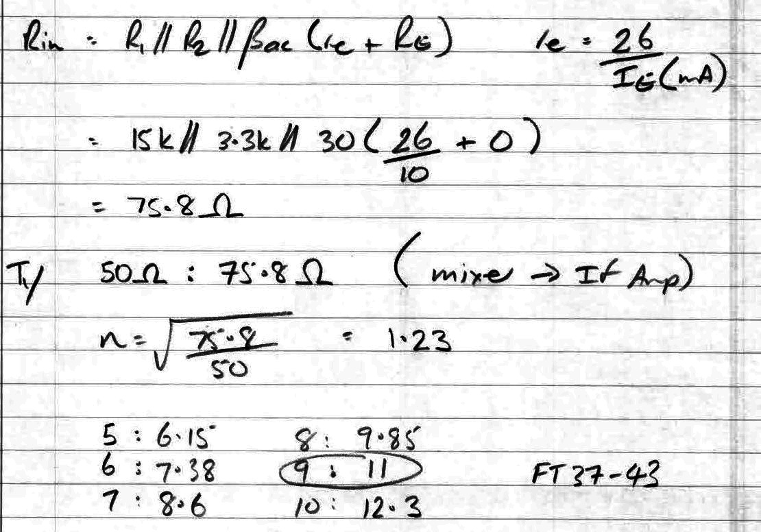
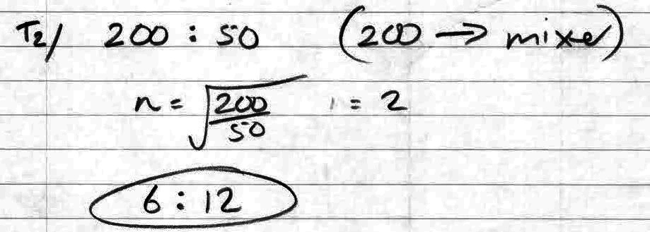
| − | * Ice = 10 mA | + | ** Input Transformer turns ratio = 1 : 1.23 (50:75.8 Ohms) |
| − | * Ve = 0.1 * Vcc = 1.2V | + | * DC operating point |
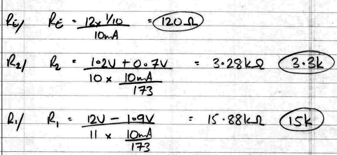
| + | ** Ice = 10 mA | ||
| + | ** Ve = 0.1 * Vcc = 1.2V | ||
=== Schematics === | === Schematics === | ||
Revision as of 18:57, 3 November 2021
Contents
RF Amplifier
- Solid State Design for the Radio Amateur?
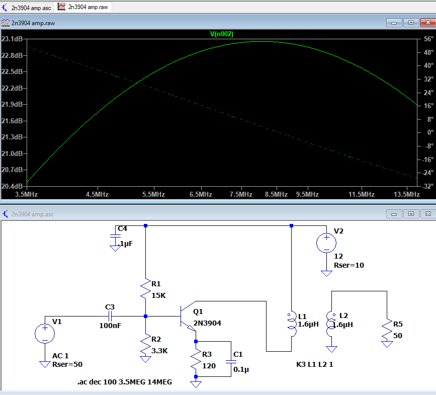
- +22 dB gain
- FT37-43 toroids
- Wideband Transformers 5 - 400 MHz
- Power Transformers 0.5 - 30 MHz
- Input Transformer turns ratio = 1 : 1.23 (50:75.8 Ohms)
- DC operating point
- Ice = 10 mA
- Ve = 0.1 * Vcc = 1.2V
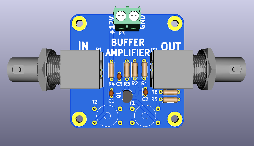
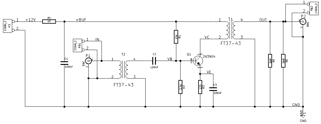
Schematics
LT Spice Simulation
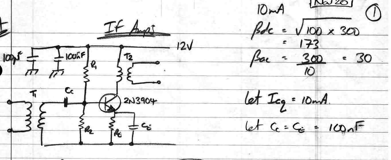
Charlie Morris Schematics
IF AMP
Video
