Difference between revisions of "RASPI-PLUS-GVS"
Blwikiadmin (talk | contribs) |
Blwikiadmin (talk | contribs) |
||
| Line 1: | Line 1: | ||
[[File:tindie-mediums.png|link=https://www.tindie.com/products/land_boards/33v5v-sensor-conn-card-for-raspberry-pi-ab/?pt=ac_prod_search]] | [[File:tindie-mediums.png|link=https://www.tindie.com/products/land_boards/33v5v-sensor-conn-card-for-raspberry-pi-ab/?pt=ac_prod_search]] | ||
| + | |||
| + | == 3.3V/5V Sensor Conn Card for Raspberry Pi A+/B+ == | ||
<video type="youtube">sp5S7JSjOhY</video> | <video type="youtube">sp5S7JSjOhY</video> | ||
Revision as of 18:29, 5 January 2020
Contents
3.3V/5V Sensor Conn Card for Raspberry Pi A+/B+
Schematic
What is it?
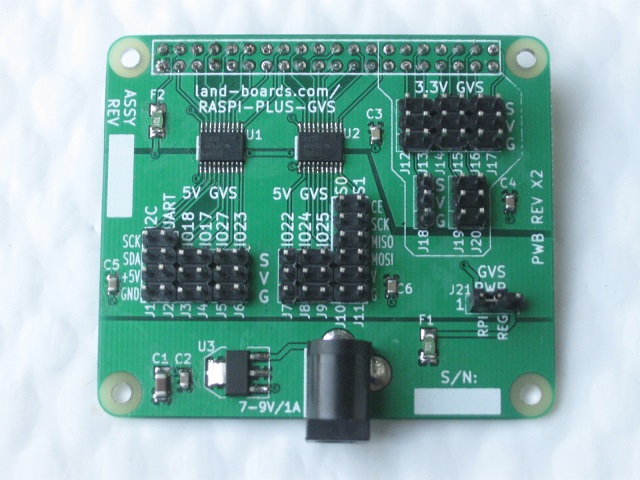
This hat (card) allows external devices to be easily connected to the Pi. It can be used for breadboard prototyping or used in real-world directly wired applications.
Why did you make it?
One of the things which you discover early on when you try to hook up external devices is that the Raspberry Pi runs at 3.3V on the I/O pins. Unfortunately, most of the parts that you want to connect to your Pi run at 5V. The way people solve that problem is to buy a prototyping card and a voltage translation breakout card and then wire the signals up by hand. That's a lot of work and not very flexible for making changes. It's also not a very stable solution. It would be much easier if that wiring was done on the a card which connects up to the Pi.
What makes it special?
This hat takes all of the I/O lines from the Raspberry Pi and brings them out to GVS (Ground/Voltage/Signal) connectors. GPIO lines get their own connectors with their own power and ground. Signals that are part of a function like I2C, UART, and SPI signals get put together onto connectors but still get power and ground on those connectors. If, for instance, you want to connect up to a 5V LCD which runs SPI you would just wire it to one of the two SPI connectors.
Schematic
Drivers/Example Code
- Github repo - Driver code

