Difference between revisions of "SPI-POTX2"
Jump to navigation
Jump to search
Blwikiadmin (talk | contribs) |
Blwikiadmin (talk | contribs) |
||
| Line 57: | Line 57: | ||
** Creates triangle wave output on both outputs | ** Creates triangle wave output on both outputs | ||
| − | == Test | + | == Factory Test Procedure == |
| + | |||
| + | * Test SPI-POTX2 card on [[RPI_PSOC5]] Test Station | ||
| + | |||
| + | === Hardware Setup === | ||
| + | |||
| + | [[FILE:RPI_SPI8_P1878-720PX.jpg]] | ||
| + | |||
| + | * [[RPI_PSOC5]] | ||
| + | ** Raspberry Pi CPU Clone | ||
| + | * [[RPI-SPI8]] | ||
| + | ** 8-channel SPI mux | ||
| + | * [[POWER-49MM]] | ||
| + | ** Distribute grounds to LEDs | ||
| + | * Cable set | ||
| + | ** 2x6 header plugs into pair of SPI ports | ||
| + | ** 4 of 2x4 connectors attach to [[LED-TEST-2]] card | ||
| + | *** (8) CE (SS) | ||
| + | *** MOSI | ||
| + | *** MISO | ||
| + | *** SCK | ||
| + | |||
| + | === Run Tests === | ||
| + | |||
| + | * Run puTTY | ||
| + | ** Find COM Port in Device Manager | ||
| + | ** 115,200 baud | ||
| + | ** RTS/CTS flow control | ||
| + | |||
| + | [[FILE:RPI_SPI8-puTTY_setup.PNG]] | ||
| + | |||
| + | * Hit ENTER to see menu | ||
| + | <pre> | ||
| + | Land Boards, LLC - RPi Card Test Station | ||
| + | 1 - Select RPP-UIO-16 Card | ||
| + | 2 - Select RPPSOC Card | ||
| + | 3 - Select RASPI-PLUS-GVS-CFG Card | ||
| + | 4 - Select RASPI-GVS Card | ||
| + | 5 - Select RASPI-PLUS-GVS Card | ||
| + | 6 - Select RPI-I2C-HUB Card | ||
| + | 7 - Select RPI-SPI8 Card | ||
| + | R - Read EEPROM | ||
| + | W - Write EEPROM | ||
| + | B - Bounce LED across Card GPIOs | ||
| + | T - Test Card | ||
| + | D - Debug Card | ||
| + | ? - Print this menu | ||
| + | </pre> | ||
| + | * Select RPI-SPI8 Card by entering 7[ENTER] | ||
| + | <pre> | ||
| + | 7 | ||
| + | Selected RPI-SPI8 card | ||
| + | </pre> | ||
| + | |||
| + | === Blink LEDs === | ||
| + | |||
| + | * Enter B[ENTER] | ||
| + | <pre> | ||
| + | B | ||
| + | Blinking the RPI-SPI8 Card LEDs, please wait | ||
| + | </pre> | ||
| + | * Bounces LEDs off across the LEDs | ||
| + | ** 8 CE signals go low one at a time | ||
| + | ** MOSI, MISO, SCK cycles one on at time | ||
| + | |||
| + | === Test Software === | ||
| + | |||
| + | * Runs on [[RPI_PSOC5]] | ||
| + | * [https://github.com/land-boards/RasPi/tree/master/RPI_PSOC5/RPI_PSOC5_CARD_TEST_STATION.cydsn GitHub repo] | ||
| + | ** [https://github.com/land-boards/RasPi/blob/master/RPI_PSOC5/RPI_PSOC5_CARD_TEST_STATION.cydsn/Test_RPI_SPI8.c Test_RPI_SPI8.c] - Bounce LED across [[LED-TEST-2]] card | ||
* Runs on [[RPI_PSOC5]] | * Runs on [[RPI_PSOC5]] | ||
Revision as of 11:54, 5 April 2022
Contents
Features
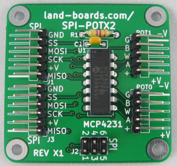
- Dual Digital potentiometer
- MCP4231 Dual Digital Pot
- 7-bit: 128 Resistors (129 Steps)
- Zero Scale to Full Scale Wiper operation
- 10K
- Other resistances optional: 5K, 50K, 100K
- Power on reset to half wiper value
- SPI Interface
- SPI Serial Interface (10 MHz, modes 0,0 & 1,1)
- High-Speed Read/Writes to wiper register
- 10 MHz (max SPI speed)
- 2.7V to 5.5V
- Daisy-chain SPI connector
- Slave Select (SS) should be star connected
- 49x49mm form factor
- (4) #4-40 mounting holes
Connectors
J1, J3 - SPI connector
- MISO
- +V
- SCK
- MOSI
- SS
- GND
J2 - SPI Connector
- Matches Arduino SPI connector pinout
- MISO
- +V
- SCK
- MOSI
- SS
- GND
POT0, POT1
- GND
- B SIDE
- WIPER
- A SIDE
- +V
Driver Software
- SPI-POT-X2 GitHub Arduino Example Code
- Creates triangle wave output on both outputs
Factory Test Procedure
- Test SPI-POTX2 card on RPI_PSOC5 Test Station
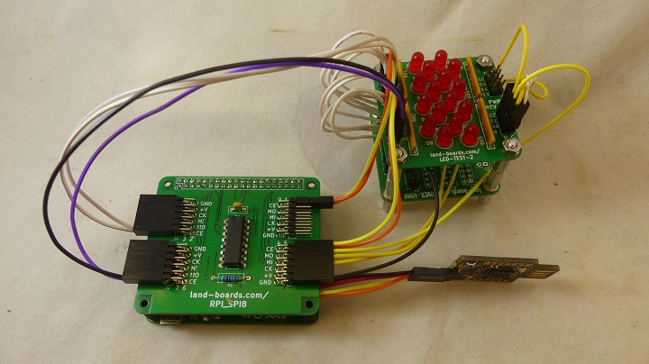
Hardware Setup
- RPI_PSOC5
- Raspberry Pi CPU Clone
- RPI-SPI8
- 8-channel SPI mux
- POWER-49MM
- Distribute grounds to LEDs
- Cable set
- 2x6 header plugs into pair of SPI ports
- 4 of 2x4 connectors attach to LED-TEST-2 card
- (8) CE (SS)
- MOSI
- MISO
- SCK
Run Tests
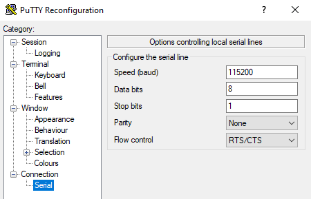
- Run puTTY
- Find COM Port in Device Manager
- 115,200 baud
- RTS/CTS flow control
- Hit ENTER to see menu
Land Boards, LLC - RPi Card Test Station
1 - Select RPP-UIO-16 Card
2 - Select RPPSOC Card
3 - Select RASPI-PLUS-GVS-CFG Card
4 - Select RASPI-GVS Card
5 - Select RASPI-PLUS-GVS Card
6 - Select RPI-I2C-HUB Card
7 - Select RPI-SPI8 Card
R - Read EEPROM
W - Write EEPROM
B - Bounce LED across Card GPIOs
T - Test Card
D - Debug Card
? - Print this menu
- Select RPI-SPI8 Card by entering 7[ENTER]
7
Selected RPI-SPI8 card
Blink LEDs
- Enter B[ENTER]
B
Blinking the RPI-SPI8 Card LEDs, please wait
- Bounces LEDs off across the LEDs
- 8 CE signals go low one at a time
- MOSI, MISO, SCK cycles one on at time
Test Software
- Runs on RPI_PSOC5
- GitHub repo
- Test_RPI_SPI8.c - Bounce LED across LED-TEST-2 card
- Runs on RPI_PSOC5
- Uses RPI_SPI8
- GitHub repo
- Test_RPI_SPI8.c - Test with SPI-POTX2 card


