Difference between revisions of "Extend IOP16 minimal example"
Jump to navigation
Jump to search
Blwikiadmin (talk | contribs) |
Blwikiadmin (talk | contribs) |
||
| Line 27: | Line 27: | ||
* Build/test | * Build/test | ||
| − | + | = Clone Sources = | |
* Clone the two repositories to the same directory level since relative paths are used for source files | * Clone the two repositories to the same directory level since relative paths are used for source files | ||
| Line 35: | Line 35: | ||
* There are a lot of extra files in the two unzipped folders (380MB) | * There are a lot of extra files in the two unzipped folders (380MB) | ||
| − | + | == Alternately download ZIP files == | |
* Alternately you can download the two ZIP files from GitHub | * Alternately you can download the two ZIP files from GitHub | ||
Revision as of 12:39, 11 April 2022
Contents
Overview
This is a guide to extending the minimal IOP example by adding IOP16 Peripherals to the minimal design
- This is not the same as Embedding the IOP16 into another design
- This guide requires general familiarity with IOP16 16-bit I/O CPU Design
- This example does not cover porting to a different FPGA card
- Will need to adjust I/O pin assignments if a different FPGA is used
Baseline Design
Starts from IOP example
- Similar to Arduino "Blink Sketch" and uses the following resources
- Timer Unit - 1 second timer
- The Timer unit can be removed if not needed
- Timer makes Blink easier
- On-board LED
- Timer Unit - 1 second timer
Steps
- Build baseline (minimal)design
- Copy baseline design
- Select/add peripherals
- Create new peripherals
- Write assembly code
- Build/test
Clone Sources
- Clone the two repositories to the same directory level since relative paths are used for source files
- Example copies files to TestBuild folder
- There are a lot of extra files in the two unzipped folders (380MB)
Alternately download ZIP files
- Alternately you can download the two ZIP files from GitHub
- Unzip these two folders into the same folder
- Rename the folders to remove the -main from the folder path
- Result
Build Minimal Design
Build Minimal Example
Start by building the minimal example in Quartus II
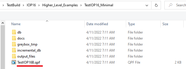
- Open the Project file (TestIOP16B.qpf) in Quartus II
- Relative path: ..\TestBuild\IOP16\Higher_Level_Examples\TestIOP16_Minimal
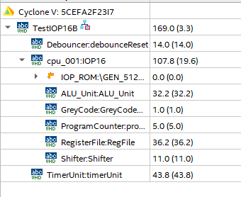
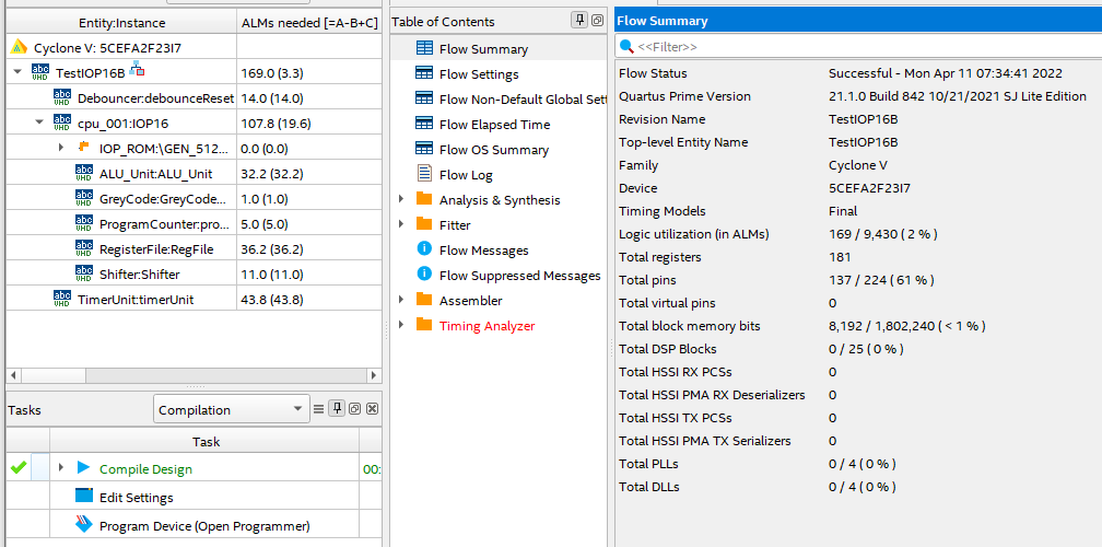
- Entities in Quartus should look like
- Build FPGA (click the blue "Start Compilation arrow)
Fix ROM File Path
- Quartus does not verify the ROM file was correct
- Could be buried in the status messages
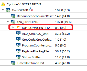
- Likely need to re-point to the ROM .MIF file since Quartus II sometimes "forgets"
- Double click on the IOP_ROM file
- Hit finish
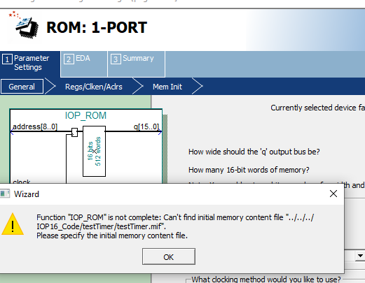
- Check for error message
- Re-point to the ROM file
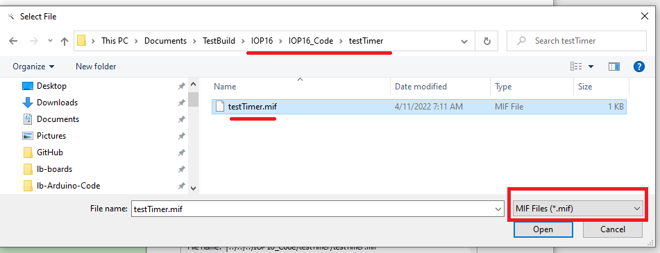
- Make sure to select .MIF file extension
Build Again / Download
- Build again
- Should be no error messages
- Result
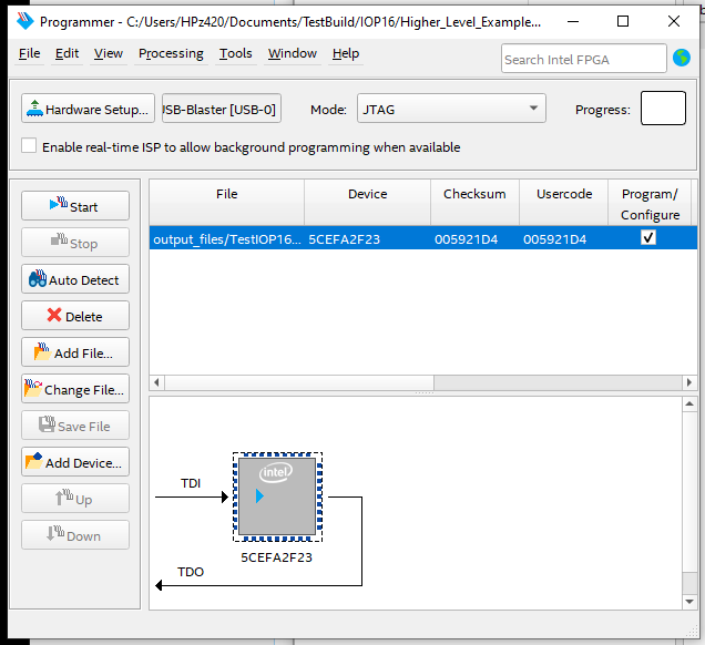
- Download
- User LED should be blinking
Copy Design
Select Peripherals
- Pick from Supported peripherals list
- Add UART peripheral
- Will set up UART in loopback
- Update Memory map in comments at start of TestIOP16B.vhd to add UART addresses
-- IOP16 MEMORY Map
-- 0X00      - KEY1 Pushbutton (R)
-- 0X00      - User LED (W)
-- 0x04-0x07 - Timer Unit
-- 0X08      - UART (Cmd/Stat) (r/w)
-- 0X09      - UART (Data) (r/w)
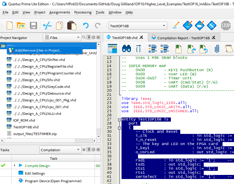
- Add UART pins to top level entity pins list
entity TestIOP16B is
  port
  (
    -- Clock and Reset
    i_clk     : in std_logic := '1';		-- Clock (50 MHz)
    i_n_reset : in std_logic := '1';		-- SW2 on FPGA the card
    -- The key and LED on the FPGA card
    i_key1    : in std_logic := '1';		-- SW1 on the FPGA card
    o_UsrLed  : out std_logic := '1';		-- USR LED on the FPGA card

    rxd1      : in std_logic := '1';		-- Hardware Handshake needed
    txd1      : out std_logic;
    cts1      : in std_logic := '1';
    rts1      : out std_logic;
    ...


Create new peripherals
Write Assembly code
Test the build


