Difference between revisions of "MyMenu"
Jump to navigation
Jump to search
Blwikiadmin (talk | contribs) |
Blwikiadmin (talk | contribs) (→Timing) |
||
| Line 176: | Line 176: | ||
* Clock on top, data on bottom | * Clock on top, data on bottom | ||
| + | * 400 KHz | ||
[[File:MyMenu-400KHz-I2C.png]] | [[File:MyMenu-400KHz-I2C.png]] | ||
Latest revision as of 19:30, 6 June 2022
Contents
Features
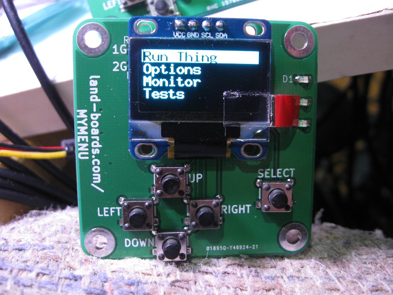
MyMenu is a self contained menu system with these features:
- 0.96" OLED
- Menu Pushbuttons
- 5 Way Keypad (Up, Down, Left, Right, Select)
- Direction, Select buttons
- 2-wire I2C (VCC, GND, CLK, DATA) interface
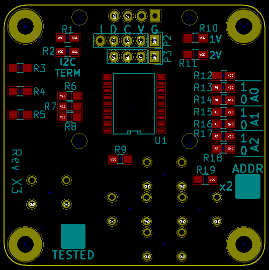
- Selectable I2C address in range 0x20-0x27 (resistor install option)
- Interrupt output line on button press
- MCP23008 I2C Port Expander
- OLED connection - mounts OLED to card and shares I2C connection to Host
- 3 LEDs
- 49x49mm card with (4) 4-40 mounting holes
MCP23008 I2C Port Expander
GPIO Port Map
GP0 - LED D3
GP1 - LED D2
GP2 - LED D1
GP3 - Select button 0 = pressed
GP4 - Right button
GP5 - Down button
GP6 - Up button
GP7 - Left button
OLED Display
- On ebay...
- There are several versions
- MyMenu requires
- 4-pin I2C version
- Rev X1-X3 requires pin Ordering VCC, GND, SCL, SDA
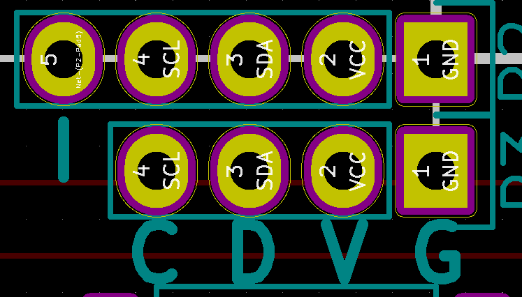
I2C Connector
Rev X4 I2C Connector
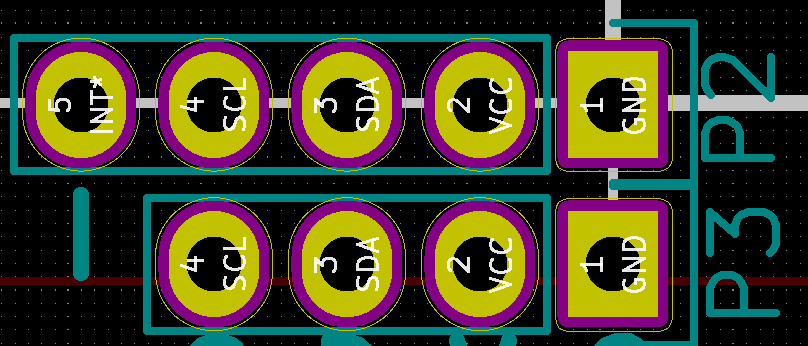
The card has a 5-pin, 0.1" spacing connector. The connector has I2C connections (CLK and DATA) plus an Interrupt line.
- GND
- VCC
- SDA
- SCL
- INT
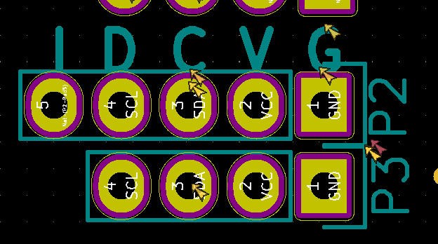
Rev X3 I2C Connector
- The card has a 5-pin, 0.1" spacing connector
- The connector has I2C connections (CLK and DATA) plus an Interrupt line
- Silkscreen is incorrect for SDA/SCL
- Pinout is
- GND
- VCC
- SDA
- SCL
- INT
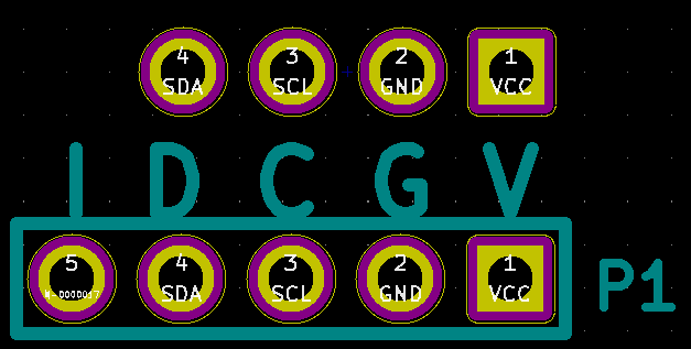
Rev X2 I2C Connector
The card has a 4-pin, 0.1" spacing connector for daisy-chaining. The connector has I2C connections (CLK and DATA).
- GND
- VCC
- SDA
- SCL
Rev X1 I2C Connector
The card has a 4-pin, 0.1" spacing connector for daisy-chaining. The connector has I2C connections (CLK and DATA).
- GND
- VCC
- SDA
- SCL
Arduino Libraries
- The Display library is decoupled from the MyMenu library and requires a separate install
MyMenu Card Library/Examples
- MyMenu library on GitHub
- Can download the ZIP file and use the ZIP library installer
- Card requires the Arduino Adafruit MCP23008 library
- Needs to be installed separately from the MyMenu library
- MCP23008 is the I2C interface chip that communicates with the buttons and LEDs
- Tested with Adafruit MCP23008 library version 1.0.1
- Driver is used to talk to the buttons/LEDs on the MyMenu card
- Driver can be installed from the Arduino IDE - search "Adafruit MCP23008"
- MyMenu card example code
Display Library - V2 Version
- V3 Version uses Oli Kraus' u8x8 library (part of u8g2 library)
- Oli Kraus' u8g2 OLED library
- Library can be installed through Arduino IDE
- Optional Land Board Menu System Code for OLED Displays - uses u8g2
- Sketch uses 8,354 bytes (25%) of program storage space. Maximum is 32,256 bytes.
- Global variables use 780 bytes (38%) of dynamic memory, leaving 1,268 bytes for local variables. Maximum is 2,048 bytes.
Display Library - Older Version (Deprecated)
- Oli Kraus' u8glib OLED library or
- Library can be installed through Arduino IDE
- Optional Land Board Menu System Code for OLED Displays - uses u8glib
- Sketch uses 10,958 bytes (33%) of program storage space. Maximum is 32,256 bytes.
- Global variables use 682 bytes (33%) of dynamic memory, leaving 1,366 bytes for local variables. Maximum is 2,048 bytes.
Other libraries - Not Recommended for New Designs
Driver/Example code
Revision History/Checkout Notes
X4 Version Changes
- Same netlist
- Fixes I2C silkscreen issues from X3
X3 Version Changes
- Added a second I2C port for daisy chain of Host I2C
- Changed host I2C pinout to G/V/SDA/SCK/INT*
- Silkscreen is wrong
- Board actually matches Sensor Shield SCK/SDA order
- Added selection resistors R10/R11 (Vcc) and R20/R21 (GND) for OLED power/ground pins
- OLEDS cards have varying pinouts, install leave open resistors to match OLED card used
- OLED card pin 1 = Vcc case
- Install R10, R21 = 0 ohms for pin 1 = VCC, pin 2 = GND
- R11, R20 left open
- OLED card pin 1 = GND case for pin 1 = GND, pin 2 = VCC
- Install R11, R20 = 0 ohms for pin 1 = GND case
- R10, R21 left open
- OLED card pin 1 = Vcc case
- Added silkscreen for MCP23008 address marking 0x2_
- Reordered reference designators for easier assembly
X2 Version Changes
- Moved LEDs to the top of the board
- Created OLED module and moved mtg holes
- Moved keys right
Timing
- Clock on top, data on bottom
- 400 KHz
- Clock/data relative timing
- Clock rise time
- Clock fall timing
