Difference between revisions of "DRIVE50"
Jump to navigation
Jump to search
Blwikiadmin (talk | contribs) (→Test) |
Blwikiadmin (talk | contribs) |
||
| Line 39: | Line 39: | ||
=== Automated Test Software Method === | === Automated Test Software Method === | ||
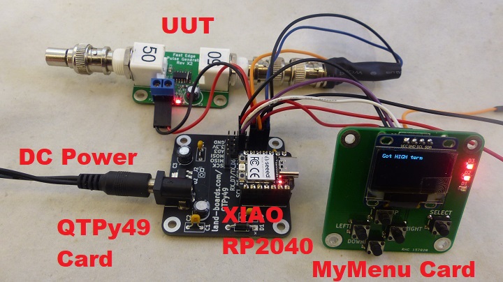
| − | * [https://github.com/land-boards/QT-Py/blob/main/CircuitPython/lbcards/PulseGen/PulseGen_DRIVE50_Test.py PulseGen_DRIVE50_Test.py] - | + | [[File:PulseGen_TestStation_P18373-720px.jpg]] |
| + | |||
| + | ==== Setup ==== | ||
| + | |||
| + | * [[QTPy49]] | ||
| + | * [[QT_Py_(RP2040_based)]] | ||
| + | ** Analog cable | ||
| + | ** GVS Cable to A1 | ||
| + | ** Analog in (BNC) to A0 on [[QTPy49]] | ||
| + | * [[MyMenu]] | ||
| + | * Power card options | ||
| + | ** Connect USB-C to the [[QT_Py_(RP2040_based)]] or | ||
| + | ** Power from 9-12V to DC jack | ||
| + | * Cables | ||
| + | ** USB-C (power option) | ||
| + | ** Power cable to UUT | ||
| + | * Terminator - dependent on build option | ||
| + | ** 50 Ohms | ||
| + | ** 75 Ohms | ||
| + | * Unit Under Test (UUT) | ||
| + | * [https://github.com/land-boards/QT-Py/blob/main/CircuitPython/lbcards/PulseGen/PulseGen_DRIVE50_Test.py PulseGen_DRIVE50_Test.py] - Test software for PulseGen and DRIVE50 cards | ||
** Stored as code.py on [[QT_Py_(RP2040_based)]] to auto-run | ** Stored as code.py on [[QT_Py_(RP2040_based)]] to auto-run | ||
| + | |||
| + | ==== Procedure ==== | ||
| + | |||
* Connect 3 pin power cable to card | * Connect 3 pin power cable to card | ||
* Connect BNC T to output of card | * Connect BNC T to output of card | ||
Revision as of 16:15, 30 July 2022
Contents
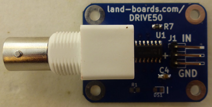
50 Ohm Driver Card
- "TTL" Level Line driver
- 50 or 75 Ohm output impedance
- BNC or SMA output connector
- 10K pull-up on input
- Card is non-inverting
- 1.5V-5.5V power
- Typically 3.3V or 5V
- 3-pin right angle 0.1" pitch input connector
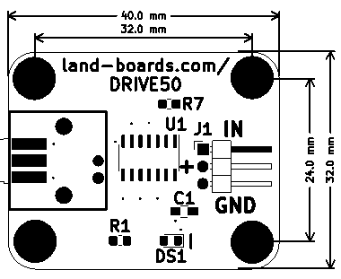
- (4) 4-40 mounting holes
Driver
- 5x paralleled 74AC14 drivers
- 24mA per pin max current output
- Symmetric high-low drive levels
- Short-circuit proof
- 5V, 250 Ohms to ground is 20 mA (pins are rated for 24 mA
- 24mA per pin max current output
- Card input has single buffer stage
- Schmitt Trigger Input
- 3.3V, 250 Ohm resistors (/5) for 50 Ohm output
- Normal output = 10 mA per pin
Test
- Manual or Automated test methods
Manual Test Method
- Supply Vcc 3.3V to 5V and ground
- Input is pulled up to Vcc
- Measure output with BNC T
- Should be 1/2 of Vcc with 50 Ohm terminator
- Should be Vcc without terminator
Automated Test Software Method
Setup
- QTPy49
- QT_Py_(RP2040_based)
- Analog cable
- GVS Cable to A1
- Analog in (BNC) to A0 on QTPy49
- MyMenu
- Power card options
- Connect USB-C to the QT_Py_(RP2040_based) or
- Power from 9-12V to DC jack
- Cables
- USB-C (power option)
- Power cable to UUT
- Terminator - dependent on build option
- 50 Ohms
- 75 Ohms
- Unit Under Test (UUT)
- PulseGen_DRIVE50_Test.py - Test software for PulseGen and DRIVE50 cards
- Stored as code.py on QT_Py_(RP2040_based) to auto-run
Procedure
- Connect 3 pin power cable to card
- Connect BNC T to output of card
- Connect BNC female from tester to BNC T male
- Install 50 terminator to other side of BNC T
- Connect USB C cable
- Display will show
PulseGen/DRIVE50 V1.1
50 Ohm card
Set/Got Low
Term High = OK
- All 3 LEDs are on


