Difference between revisions of "SIMPLE-6802"
Jump to navigation
Jump to search
Blwikiadmin (talk | contribs) |
Blwikiadmin (talk | contribs) |
||
| Line 24: | Line 24: | ||
* 0xC000-0xCFFF 16KB EPROM | * 0xC000-0xCFFF 16KB EPROM | ||
| − | == Connectors == | + | == Headers / Connectors == |
=== J1 - RS-232 Serial === | === J1 - RS-232 Serial === | ||
| Line 37: | Line 37: | ||
# N/C | # N/C | ||
# N/C | # N/C | ||
| + | |||
| + | === J2 / J5 - EPROM/EEPROM Select Jumpers === | ||
| + | |||
| + | {| class="wikitable" | ||
| + | ! PART | ||
| + | ! J2 PIN 1 | ||
| + | ! J5 PIN 27 | ||
| + | |- | ||
| + | | 27128 EPROM | ||
| + | | VPP (5V) | ||
| + | | PGM (5V) | ||
| + | |- | ||
| + | | 27C256 EPROM | ||
| + | | VPP (5V) | ||
| + | | A14 (GND) | ||
| + | |- | ||
| + | | 27C512 EPROM | ||
| + | | A15 (GND) | ||
| + | | A14 (GND) | ||
| + | |- | ||
| + | | SST27SF256 EEPROM | ||
| + | | VPP (5V) | ||
| + | | A14 (GND) | ||
| + | |- | ||
| + | | SST27SF512 EEPROM | ||
| + | | A15 (GND) | ||
| + | | A14 (GND) | ||
| + | |- | ||
| + | |} | ||
=== J3 - FTDI / TTL Serial === | === J3 - FTDI / TTL Serial === | ||
Revision as of 17:34, 12 September 2022
Contents
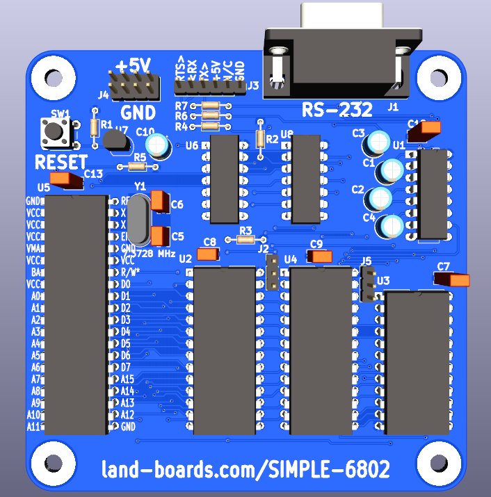
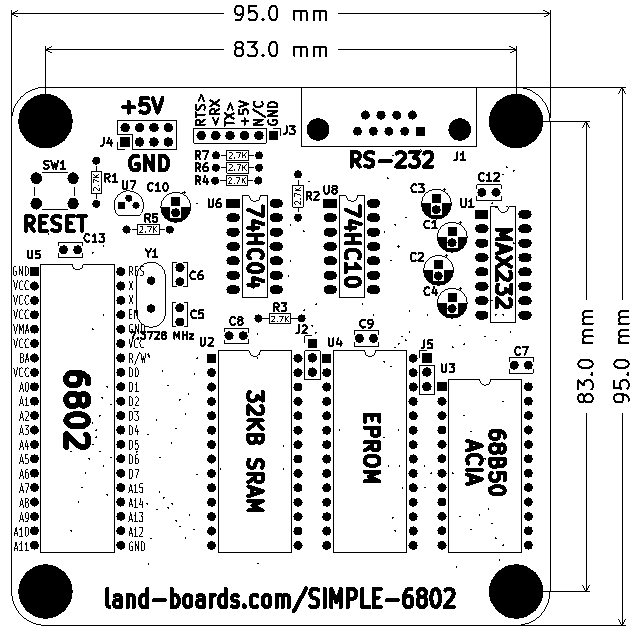
Features
- Build of Grant Searles's Simple 6809 CPU
- Runs MIKBUG
- 68B02 CPU
- 1.8432 MHz
- 32KB SRAM
- 16KB EPROM/EEPROM
- 68B50 Serial Port (ACIA)
- RS-232 port
- Header for FTDI
- 115,200 baud
- Reset switch with optional Power Supervisor
- 95x95mm card
- (4) 6-32 mounting holes
Memory Map
- 0x0000-0x7FFF 32KB SRAM
- 0x8000-0x9FFF Free Space (8KB)
- 0xA000-0xBFFF Serial (ACIA)
- 0xC000-0xCFFF 16KB EPROM
Headers / Connectors
J1 - RS-232 Serial
- N/C
- Receive
- Transmit
- Loop to pin 6
- GND
- Loop to pin 4
- RTS
- N/C
- N/C
J2 / J5 - EPROM/EEPROM Select Jumpers
| PART | J2 PIN 1 | J5 PIN 27 |
|---|---|---|
| 27128 EPROM | VPP (5V) | PGM (5V) |
| 27C256 EPROM | VPP (5V) | A14 (GND) |
| 27C512 EPROM | A15 (GND) | A14 (GND) |
| SST27SF256 EEPROM | VPP (5V) | A14 (GND) |
| SST27SF512 EEPROM | A15 (GND) | A14 (GND) |
J3 - FTDI / TTL Serial
- GND
- RTS* (out)
- +5V
- Receive (in)
- Transmit (out)
- N/C
J4 - 5V Power
- 2x4 header

