Difference between revisions of "Noise Generator on ER-PROTO-01"
Jump to navigation
Jump to search
Blwikiadmin (talk | contribs) |
Blwikiadmin (talk | contribs) |
||
| Line 37: | Line 37: | ||
* Add 10 Ohm resistor U1-4 to +12V | * Add 10 Ohm resistor U1-4 to +12V | ||
* Add jumper U1-11 to GND | * Add jumper U1-11 to GND | ||
| − | * Add jumper U1- | + | * Add jumper U1-8 to U1-9 (Blue loopback) |
| − | * Install 1K J1-8 to Open bus | + | * Add jumper U1-6 to U1-7 (White loopback) |
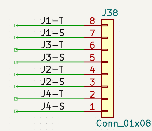
| − | * Install 1K J3-6 to Open bus | + | * Install 1K J1-8 to Open bus row (J1-T) - White noise out |
| − | * Install 1K J4-4 to Open bus | + | * Install 1K J3-6 to Open bus row (J3-T) - Blue noise out |
| + | * Install 1K J4-4 to Open bus row (J4-T) - Pink noise out | ||
Revision as of 20:34, 15 November 2022
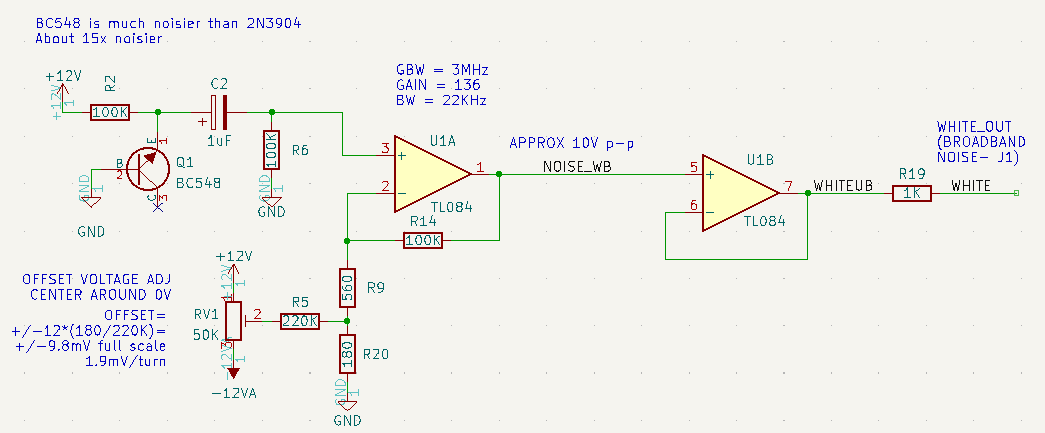
- White Noise Generator
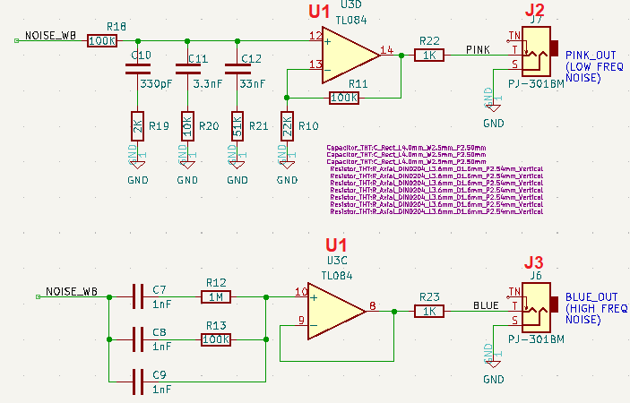
- Blue/Pink Noise
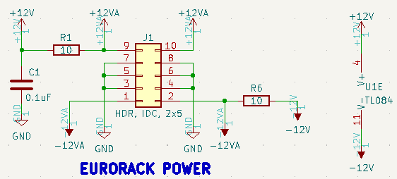
- U1 Power
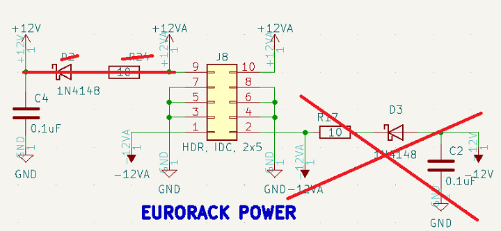
- Eurorack Power
Connectors
- Jacks
Build
On Controls Card
- Install J1, J3, J4
- Wire J1-S to J3-S
- Wire J3-S to J4-S
On Daughtercard
- Wire J38-3 or J38-5 to nearby GND
- Install U1 14 pin socket near "middle of card
- Pin 4 goes towards +12V
- Add 10 Ohm resistor U1-4 to +12V
- Add jumper U1-11 to GND
- Add jumper U1-8 to U1-9 (Blue loopback)
- Add jumper U1-6 to U1-7 (White loopback)
- Install 1K J1-8 to Open bus row (J1-T) - White noise out
- Install 1K J3-6 to Open bus row (J3-T) - Blue noise out
- Install 1K J4-4 to Open bus row (J4-T) - Pink noise out
