Difference between revisions of "HW-9 VFO"
Jump to navigation
Jump to search
Blwikiadmin (talk | contribs) |
Blwikiadmin (talk | contribs) |
||
| Line 56: | Line 56: | ||
** Rx | ** Rx | ||
** BFO | ** BFO | ||
| + | |||
| + | ==== VFO TX ==== | ||
| + | |||
| + | * From 5.9993-5.7493 MHz | ||
| + | |||
| + | ==== VFO RX ==== | ||
| + | |||
| + | * RIT knob is taken in through an A/D and adjusts the frequency plus/minus 1 KHz | ||
| + | |||
| + | ==== BFO ==== | ||
| + | |||
| + | * 8.8314 MHz in receive | ||
| + | * 8.8307 MHz in transmit | ||
=== Low Pass Filters === | === Low Pass Filters === | ||
Revision as of 22:53, 26 September 2020
This is a work in process - Gathering pieces.
Contents
Features
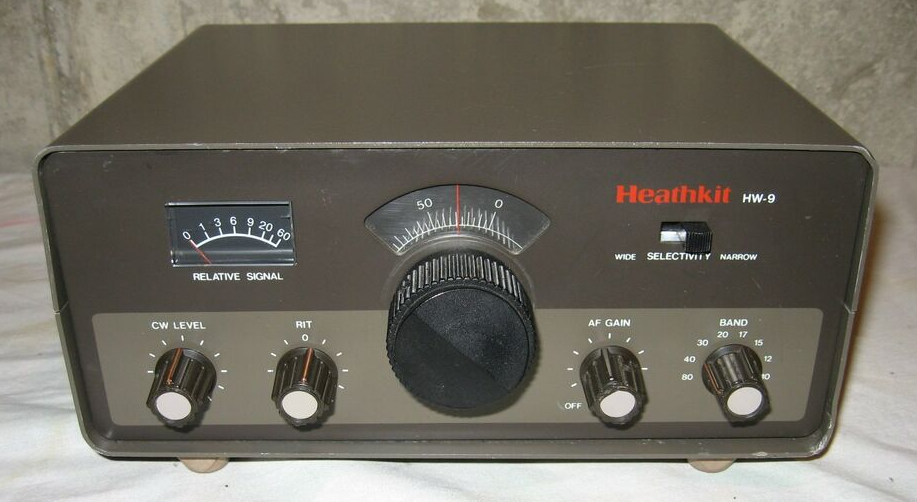
- Replace HW-9 internal VFO with a digital VFO
- HW-9 VFO has legendary issues
- Mechanical issues with vernier
- Drift due to thermal
- Lack of resolution
- HW-9 VFO has legendary issues
- Fits within HW-9 VFO Box
- Controls Tx/Rx/BFO frequencies with rotary encoder
- 10 Hz steps
- DD1306 OLED Display
- I2C Interface
- "Curved" display
- Uses RIT control on HW-9
- +/- 1 KHz RIT
- Blue Pill Microprocessor
- Arduino compatible
- 3.3V
- Understands band switch for MHz displayed
- Si5351 Oscillator
- I2C Interface
- 3 Outputs
- Transmit frequency
- Receiver frequency include offset plus RIT
- BFO frequency
- Low pass filters to turn square waves to sine waves
- 27 MHz crystal
Parts
Blue Pill Card
128x32 OLED
Rotary Encoder/Breakout Board
- Includes pushbutton Switch
- Needs R/C filter on output
- Includes Pull-Up resistors
- Simple Rotary Encoder Arduino library
- Library for the Arduino environment for using a rotary encoder as an input
Si5351 FrequencyGenerator
- 3 outputs
- Tx
- Rx
- BFO
VFO TX
- From 5.9993-5.7493 MHz
VFO RX
- RIT knob is taken in through an A/D and adjusts the frequency plus/minus 1 KHz
BFO
- 8.8314 MHz in receive
- 8.8307 MHz in transmit
Low Pass Filters
- 6 MHz
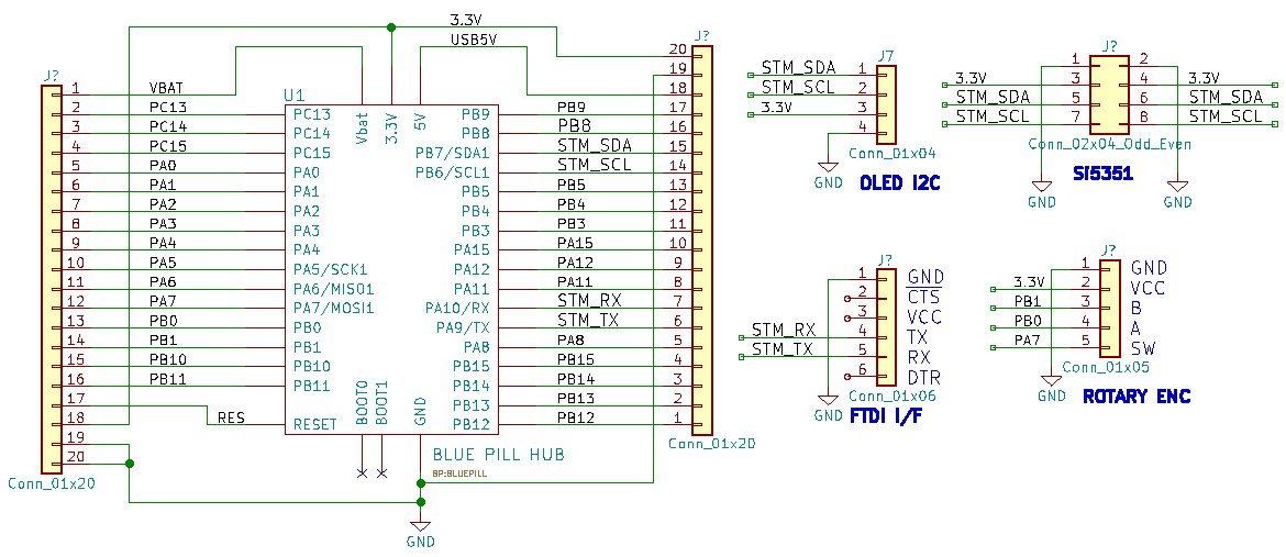
Schematic
Libraries
- VFO and BFO with Si5351A, OLED and Arduino
- U8g2: Library for monochrome displays, version 2
- Si5351 Library for Arduino
- Universal Digital VFO Si570/Si5351
- Adafruit_Si5351
- Si5351 Library for avr-gcc
- vk3hn_VFO_controller
- Simple BFO with si5351 controlled by Arduino
Videos

