Difference between revisions of "HW-9 VFO"
Jump to navigation
Jump to search
Blwikiadmin (talk | contribs) (→Videos) |
Blwikiadmin (talk | contribs) |
||
| Line 211: | Line 211: | ||
<video type="youtube">rABYJi0vm7g</video> | <video type="youtube">rABYJi0vm7g</video> | ||
| + | 4 Led's in the HW-9 taking only 5 MA when wired in series with a 2200 ohm 1/4 watt resistor . A total of 20 MA to light the dial and meter. The space between the front panel and the chassis here is very small so the tiny LED's are required to do the job . | ||
Revision as of 10:34, 30 October 2020
This is a work in process - Gathering pieces.
Contents
Features
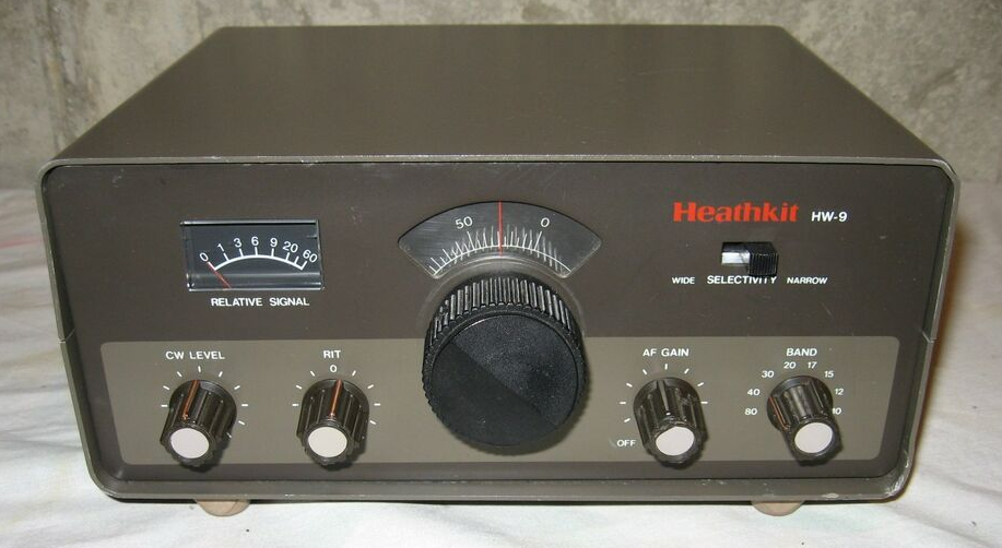
Replace HW-9 internal VFO with a digital VFO
- HW-9 VFO has legendary issues
- Mechanical issues with vernier
- Drift due to thermal
- Lack of resolution
- Backwards dial
- Fits within HW-9 VFO Box
- Controls Tx/Rx/BFO frequencies with rotary encoder
- 10 Hz steps
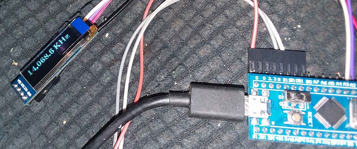
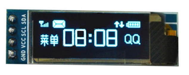
- DD1306 OLED Display
- I2C Interface
- "Curved" display
- Uses RIT control on HW-9
- +/- 1 KHz RIT
- Blue Pill Microprocessor
- Arduino compatible
- 3.3V
- Understands band switch for MHz displayed
- Si5351 Oscillator
- I2C Interface
- 3 Outputs
- Transmit frequency
- Receiver frequency include offset plus RIT
- BFO frequency
- Low pass filters to turn square waves to sine waves
- 27 MHz crystal
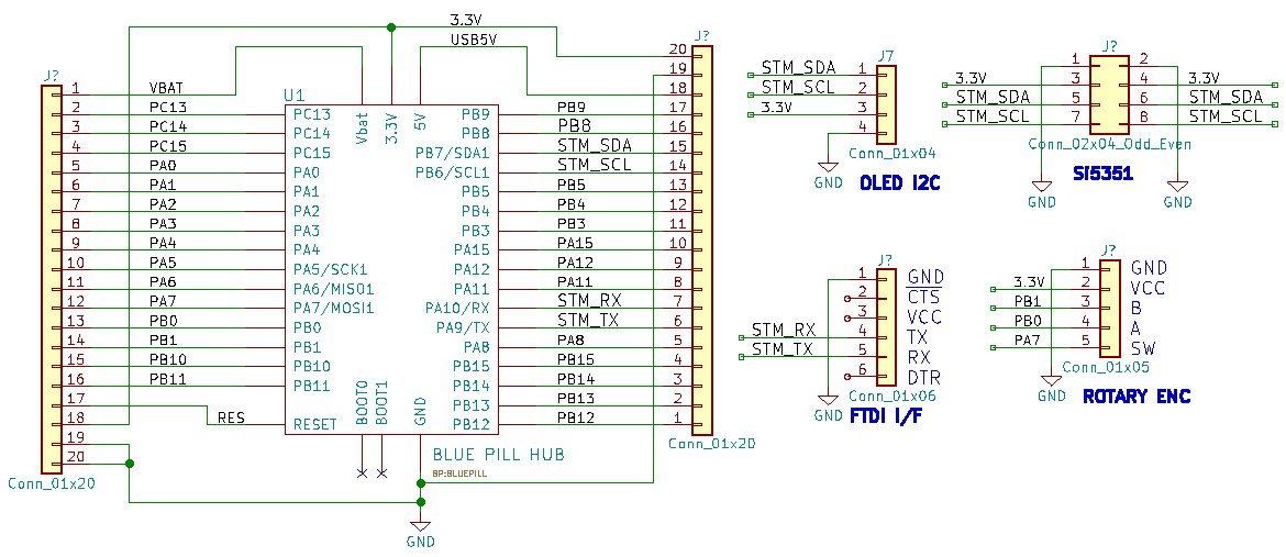
Schematic
Connections to Radio
- RIT pot
- Connects to Analog input
- Polled occasionally while in receive
- Connects to Analog input
- Band switch
- SW1 9V
- T/R - transmit/receive
Parts
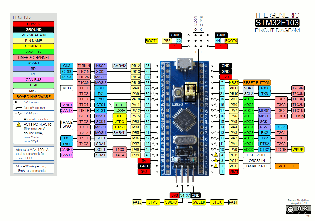
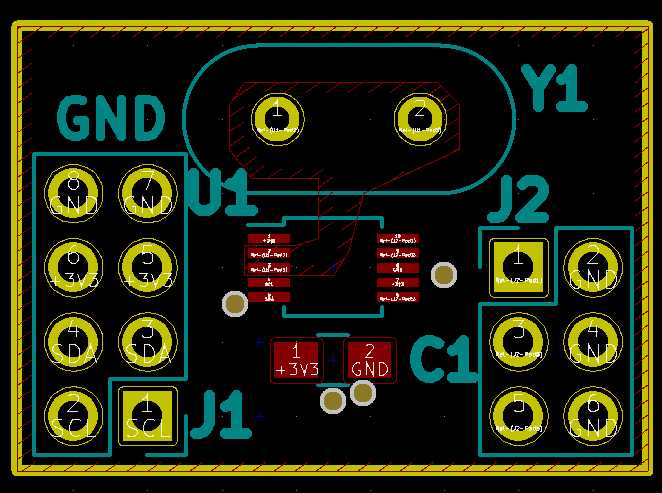
Blue Pill Card
- 3.3V operation work without level shifters for I2C
- OLED can run from 3.3V
- Si5351 can only run from 3.3V
- Used right angle headers and Dupont cables
- Replaced BOOT 0,1 jumpers
- Jumper on BOOT1
- Switch on BOOT0 - easier to download code
- Download via serial
- Arduino IDE
128x32 OLED
Arduino Library for OLED
U8G2_SSD1306_128X32_UNIVISION_F_HW_I2C u8g2(U8G2_R0, /* reset=*/ U8X8_PIN_NONE); // STM32, Ebay OLED
u8g2.setFont(u8g2_font_ncenB14_tr);
Hello World Code
U8G2_SSD1306_128X32_UNIVISION_F_HW_I2C u8g2(U8G2_R0, /* reset=*/ U8X8_PIN_NONE);   // STM32, Ebay OLED

void setup(void) {
  u8g2.begin();
}

void loop(void) {
  u8g2.clearBuffer();			// clear the internal memory
  u8g2.setFont(u8g2_font_ncenB08_tr);	// choose a suitable font
  u8g2.drawStr(0,10,"Hello World!");	// write something to the internal memory
  u8g2.sendBuffer();			// transfer internal memory to the display
  delay(1000);
}
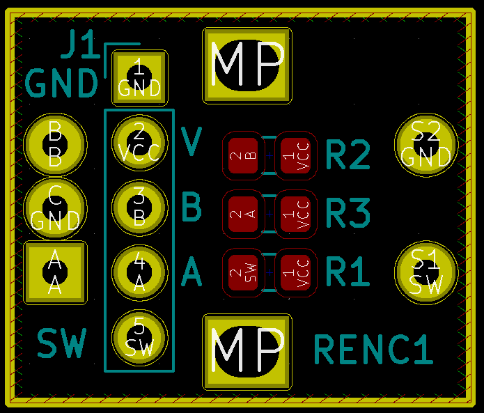
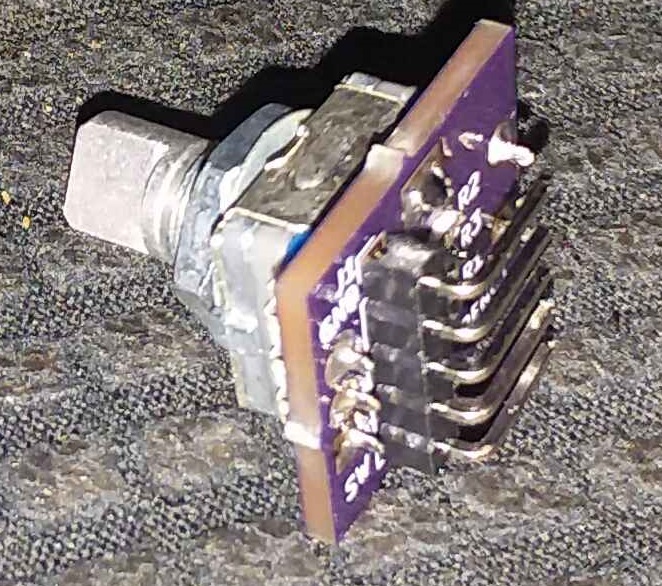
Rotary Encoder/Breakout Board
- Includes pushbutton Switch
- Includes Pull-Up resistors
- Needs R/C filter on output for debounce
- Reading Rotary Encoders - Arduino reference
- Simple Rotary Encoder Arduino library
- Library for the Arduino environment for using a rotary encoder as an input
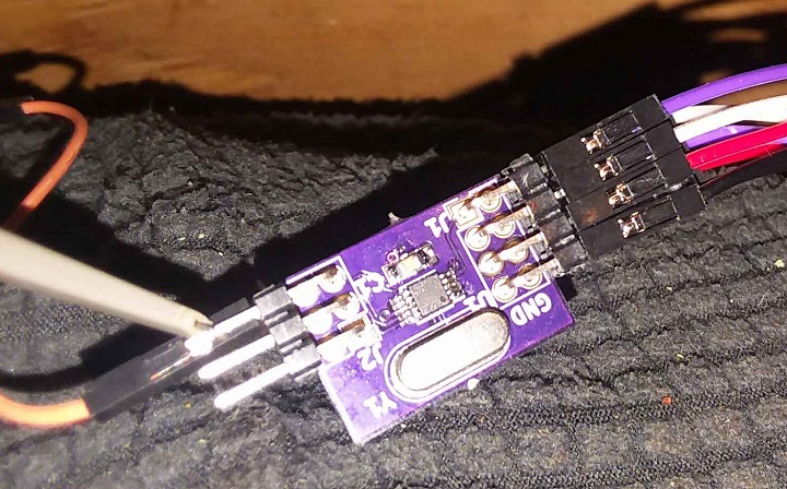
Si5351 Frequency Generator
- I2C Daisy-chain connector
- 3 outputs
- Tx
- Rx (may not need to use separate output)
- BFO - could be adjusted
Measurements
VFO TX
- 250 KHz range
- From 5.9993-5.7493 MHz
VFO RX
- RIT knob is taken in through an A/D and adjusts the receive frequency plus/minus 1 KHz
BFO
- 8.8314 MHz in receive
- 8.8307 MHz in transmit
- 700 Hz difference but could be adjusted
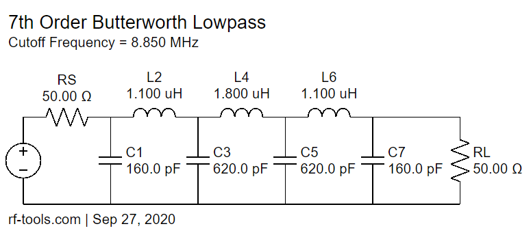
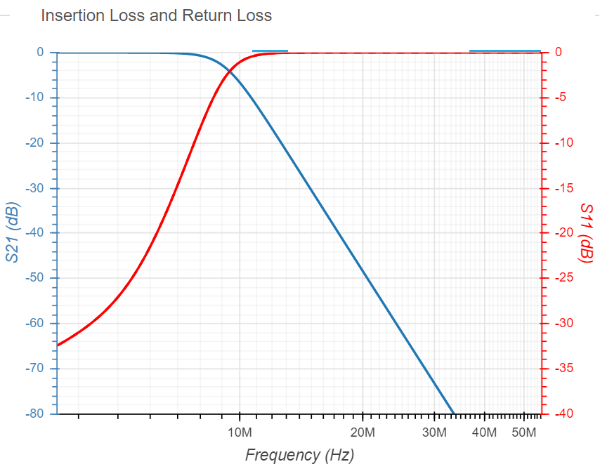
Low Pass Filters
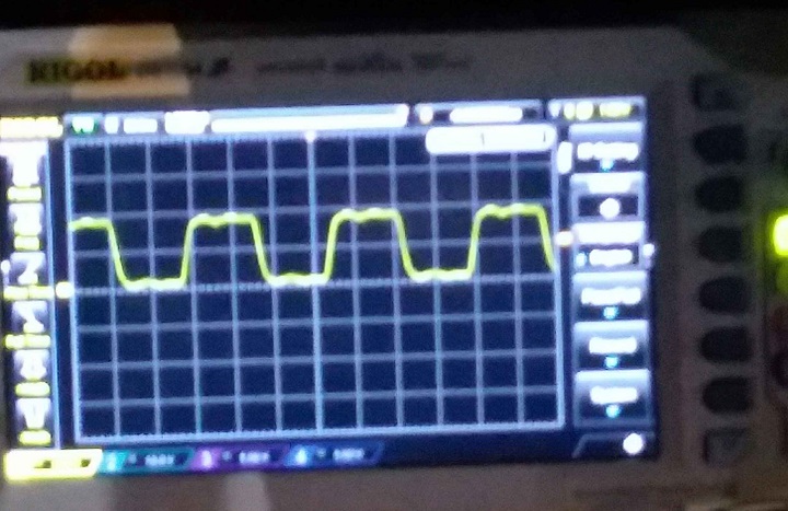
- Si5351 has square wave outputs
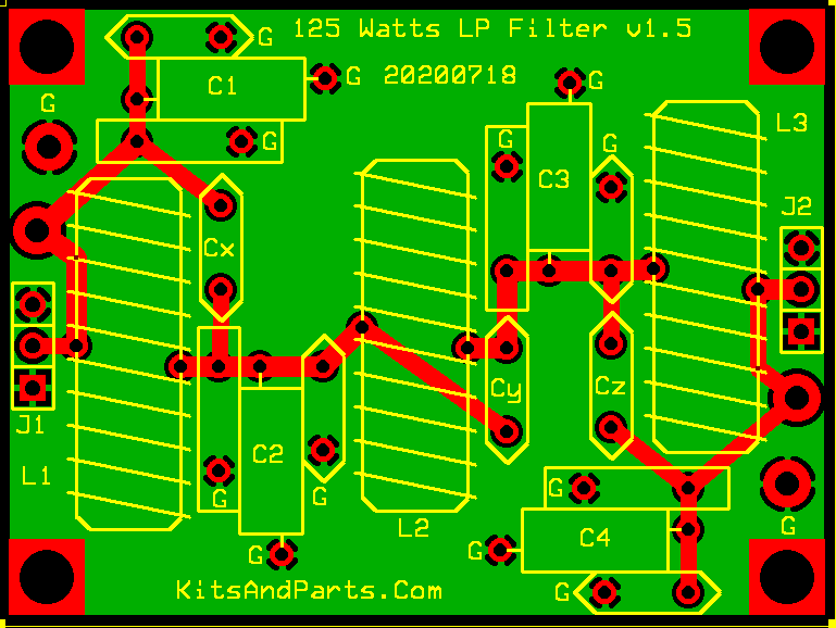
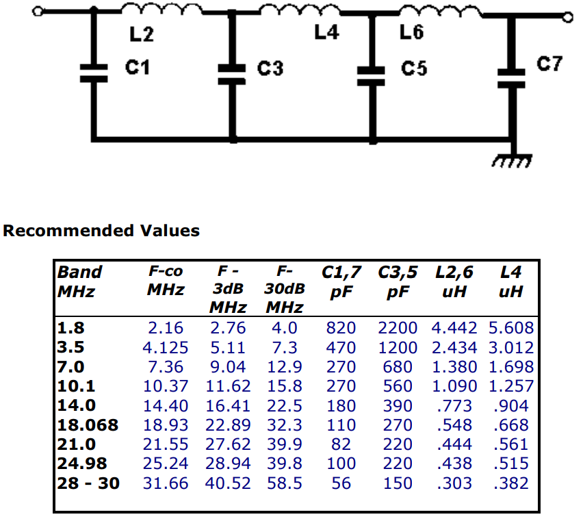
- LP filter can be used to change squarewave into sinewave
- LC Filters Design Tool - calculator
- Kits and Parts dot Com
- Build a 7-pole Universal Low Pass Filter for HF
- Butterworth
- Replace with SMT card?
- VFO and BFO frequencies are outside the bands (deliberately to void collisions)
BFO Filter
- 8.8314 MHz in receive
- 8.8307 MHz in transmit
Libraries/Example Code
- Land Boards Application
- VFO and BFO with Si5351A, OLED and Arduino
- U8g2: Library for monochrome displays, version 2
- Si5351 Library for Arduino
- Universal Digital VFO Si570/Si5351
- Adafruit_Si5351
- Si5351 Library for avr-gcc
- vk3hn_VFO_controller
- Simple BFO with si5351 controlled by Arduino
Videos
HW-9 Mods
4 Led's in the HW-9 taking only 5 MA when wired in series with a 2200 ohm 1/4 watt resistor . A total of 20 MA to light the dial and meter. The space between the front panel and the chassis here is very small so the tiny LED's are required to do the job .
