Difference between revisions of "DigIO16-I2C"
Jump to navigation
Jump to search
Blwikiadmin (talk | contribs) |
Blwikiadmin (talk | contribs) |
||
| Line 21: | Line 21: | ||
== Connectors == | == Connectors == | ||
| + | |||
| + | == J1 - Power Connector (Optional) == | ||
| + | |||
| + | [[File:DIGIO16-I2C-X2-J1-POWER.PNG]] | ||
| + | |||
| + | == J2, J3 - Daisy-chained I2C Connectors == | ||
| + | |||
| + | [[File:DIGIO16-I2C-X2-J2-I2C.PNG]] | ||
| + | |||
| + | == J4 - Address Base Jumpers == | ||
| + | |||
| + | * Install for address bit = 0 | ||
| + | |||
| + | [[File:DIGIO16-I2C-X2-J4-ADR.PNG]] | ||
| + | |||
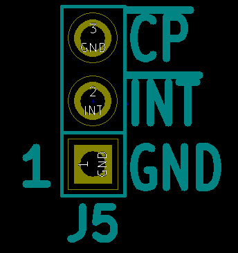
| + | == J5 - Interrupt/Card Present == | ||
| + | |||
| + | [[File:DIGIO16-I2C-X2-J5-INT.PNG]] | ||
| + | |||
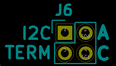
| + | == J6 - I2C Terminators == | ||
| + | |||
| + | [[File:DIGIO16-I2C-X2-J6-I2C-TERM.PNG]] | ||
| + | |||
| + | == J7 - Write Enable Jumper == | ||
| + | |||
| + | * Install to enable writes | ||
| + | |||
| + | [[File:DIGIO16-I2C-X2-J7-WR-ENABLE.PNG]] | ||
| + | |||
| + | == == | ||
| + | |||
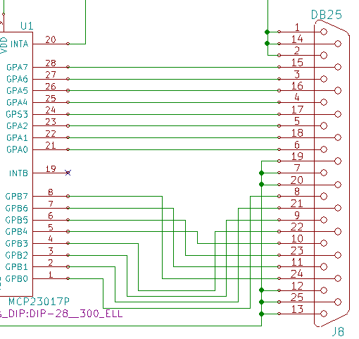
| + | [[File:DIGIO16-I2C-X2-J8-DIGIO.PNG]] | ||
== Schematic == | == Schematic == | ||
Revision as of 17:28, 1 January 2020
Contents
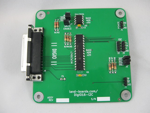
Features
- 16 bit GPIO
- MCP23017 I2C Parallel I/O
- I2C host interface
- 100/400 KHZ operation
- 25mA sink/source capability per I/O
- Jumper selectable terminators
- 3-bit address (Jumper selectable) - Up to 8 boards
- I2C Connector
- Daisy-chained 4-pin host interface connector (Ground, Power, Clock, Data)
- Power Connector
- DB-25 Connector for GPIO lines
- 24LC024 Personality EEPROM
- 3.3V or 5V operation
- Compatible with Arduino, Raspberry Pi, BeagleBone Black
- 95x95mm form factor
- (4) 6-32 mounting holes - one on each corner
Connectors
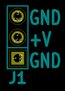
J1 - Power Connector (Optional)
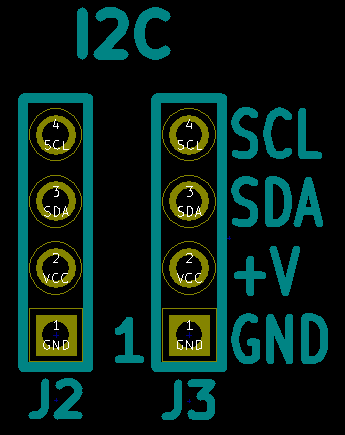
J2, J3 - Daisy-chained I2C Connectors
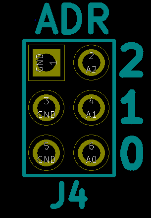
J4 - Address Base Jumpers
- Install for address bit = 0
J5 - Interrupt/Card Present
J6 - I2C Terminators
J7 - Write Enable Jumper
- Install to enable writes
