Difference between revisions of "0/10/20/30 dB Attenuator"
Jump to navigation
Jump to search
Blwikiadmin (talk | contribs) (Created page with "== 0/10/20/30 dB Attenuator == file:ATTEN4_CHINA_PCB.PNG") |
Blwikiadmin (talk | contribs) |
||
| Line 1: | Line 1: | ||
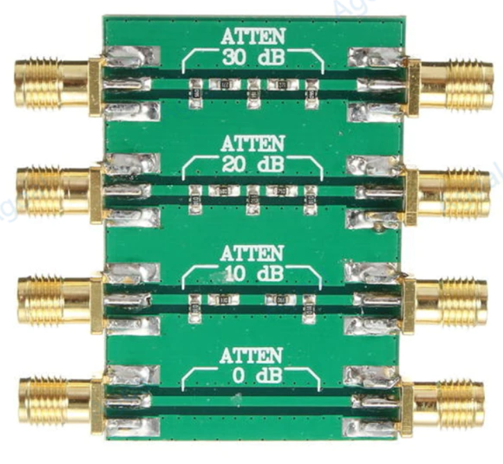
| − | + | * DC-4.0GHz 200mW DC 4.0GHz RF Fixed Attenuator SMA Double Female Head 0dB 10dB 20dB 30dB | |
[[file:ATTEN4_CHINA_PCB.PNG]] | [[file:ATTEN4_CHINA_PCB.PNG]] | ||
| + | |||
| + | == Specs == | ||
| + | |||
| + | * Frequency range: DC - 4.0GHz | ||
| + | * Maximum power: 23dBm (200mW) | ||
| + | * Standing wave ratio: ≤ 1.20 | ||
| + | * System impedance: 50Ω | ||
| + | * RF interface: SMA double female head (Outer screw inner hole) | ||
| + | * Attenuation: | ||
| + | ** Direct: 0dB (reference) | ||
| + | ** Level 1: 10 ± 0.8 dB | ||
| + | ** Level 2: 20 ± 1.1 dB | ||
| + | ** Level 3: 30 ± 1.5dB | ||
Revision as of 15:14, 3 October 2021
- DC-4.0GHz 200mW DC 4.0GHz RF Fixed Attenuator SMA Double Female Head 0dB 10dB 20dB 30dB
Specs
- Frequency range: DC - 4.0GHz
- Maximum power: 23dBm (200mW)
- Standing wave ratio: ≤ 1.20
- System impedance: 50Ω
- RF interface: SMA double female head (Outer screw inner hole)
- Attenuation:
- Direct: 0dB (reference)
- Level 1: 10 ± 0.8 dB
- Level 2: 20 ± 1.1 dB
- Level 3: 30 ± 1.5dB
