Difference between revisions of "BLACK-PILL-HUB"
Jump to navigation
Jump to search
Blwikiadmin (talk | contribs) |
Blwikiadmin (talk | contribs) |
||
| Line 70: | Line 70: | ||
=== P3 - FTDI Module === | === P3 - FTDI Module === | ||
| − | * Not as necessary on the Black Pill card since downloads can be done with the [[BLACK-PILL-HUB# | + | * Not as necessary on the Black Pill card since downloads can be done with the [[BLACK-PILL-HUB#DFU_Programming DFU|mode]] |
* Cheap FT232 module pinout | * Cheap FT232 module pinout | ||
* Remove 6 pin right angle header | * Remove 6 pin right angle header | ||
Revision as of 19:03, 11 December 2021
Contents
Features
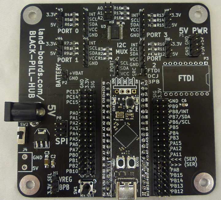
- Carrier for the STM32 Black Pill Board
- STM32F4XX|STM32F401/411 CPU
- AliExpress listing
- I2C Hub - PCA9544A
- 4-channel
- Independent 3.3V/5V power for each channel
- Separate interrupts for each channel
- GVS connections for Black Pill pins
- Reset switch
- Power options
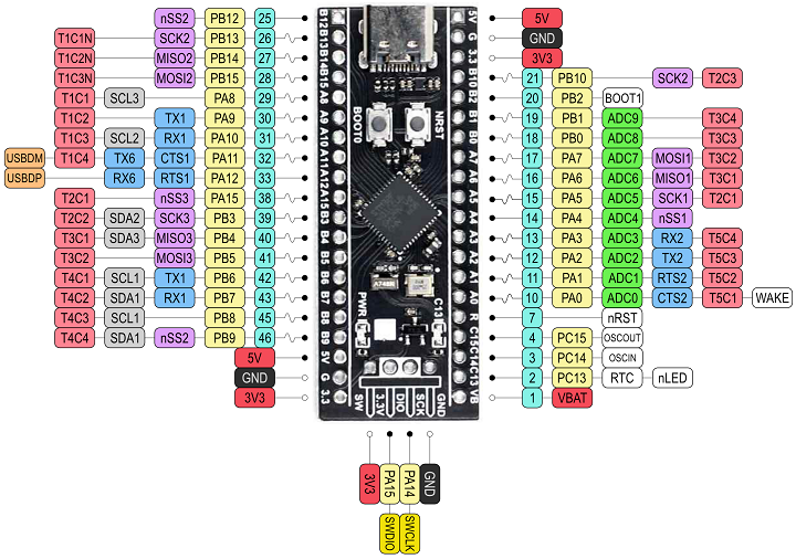
Black Pill Module
Not pin compatible with Blue Pill due to power pin locations
Reserved Pins
- PA0 - On-board USER KEY - needs INPUT_PULLUP
- PC13 - On-board LED
- PB2 - BOOT1
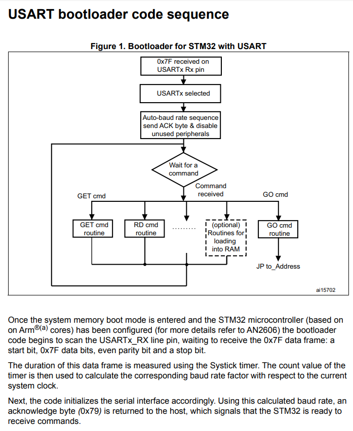
- Pulling this pin down by external hardware causes the board to boot to serial
- Can be ignored by holding both reset and BOOT1 buttons on the Black Pill card
- Release reset button first
- PA11 - USB-M
- PA12 - USB-P
- PA9 - Serial TX1
- PA10 - Serial RX1
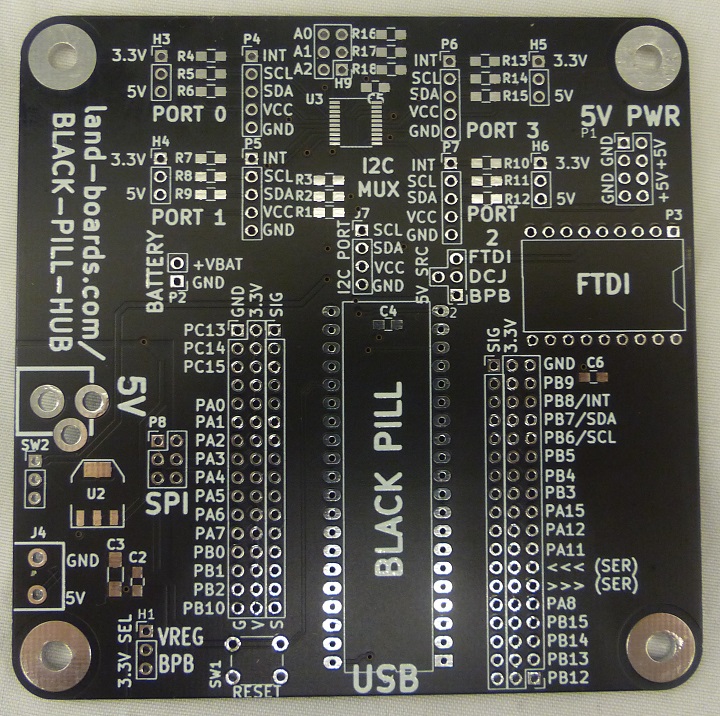
Connectors
J1 - 5V power
- DC jack
- 5V
- Center positive
J4 - 5V Power
- 5mm terminal block
J7 - I2C
- The I2C interface that goes to the I2C hub part
- SCL (PB6)
- SDA (PB7)
- 3.3V
- GND
P1 - 5V
- 2x4 header with 5V from H2 (Rev 4 card)
P2 - Vbattery
- Battery power to the Black Pill board
- GND
- Vbat
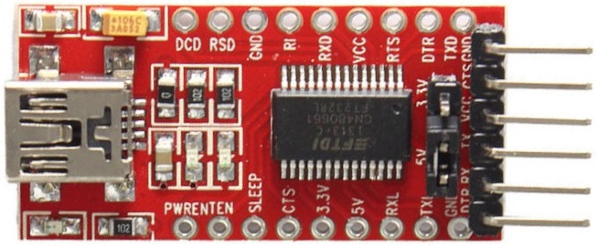
P3 - FTDI Module
- Not as necessary on the Black Pill card since downloads can be done with the mode
- Cheap FT232 module pinout
- Remove 6 pin right angle header
P4, P5, P6, P7 - I2C Interfaces #0-#3
- INT*
- SCL
- SDA
- VCC
- GND
P8 - SPI
- PA6 (MISO)
- 3.3V
- PA5 (SCK)
- PA7 (MOSI)
- RES
- GND
P11/P12 - GVS Connector
- Ground, Power, Signal pins
- Pin near Black pill is signal
- PC13
- PC14
- PC15
- N/C
- PA0
- PA1
- PA2
- PA3
- PA4
- PA5/SCK1
- PA6/MISO1
- PA7/MOSI1
- PB0
- PB1
- PB2
- PB10
P12/P13 - GVS Connector
- Ground, Power, Signal pins
- Pin near Black pill is signal
- GND
- PB9
- I2C_INT (PB8)
- I2C_SDA (PB7)
- I2C_SCL (PB6)
- PB5
- PB4
- PB3
- PA15
- PA12
- PA11
- RX
- TX
- PA8
- PB15
- PB14
- PB13
- PB12
Headers
H1 - 3.3V source select
- 1-2 = Power from 5V to 3.3V regulator
- 2-3 = Power from Black Pill board 3.3V regulator
H2 - 5V Power Source
- T-shaped header
- Up - Power 5V from FTDI 5V
- Down - Power 5V from Black Pill Hub USB power
- Left - Power 5V from DC Jack
H3, H4, H5, H6 - I2C Power
- Select the power to/from the (4) I2C interfaces
- Install in one of the two positions to power the external I2C interface from the Hub board
- Remove if power comes in from external I2C interface
- 3.3V
- 5V
H9 - Hub Chip Address
- Select the 3-bit (A0-A2) address of the PCA9544A I2C hub
- Remove for 1, install for 0
Switches
SW1 - Reset Switch
- Press to reset Black Pill board
SW2 - Switch on/off J1, J4 power source
Schematic
- Board has silkscreen with rev on rear
- BLACK-PILL-HUB Schematic Rev 1
- Has title block errors, title. rev
- BLACK-PILL-HUB Schematic Rev 2
Software
Testing
- Arduino Based Test Station
- Issue with library
Programming
DFU Programming
- Steps from Programming|Program STM32 Black Pill (STM32F401 / F411) with Arduino IDE (Windows OS)
- Add the URL to Additional Board Manager URLs text box:
- Go to Tools > Board > Boards Manager
- Search for STM32, select latest version and click Install.
- Download and install STM32CubeProg from ST.com: [1]
- Start the STM32CubeProg
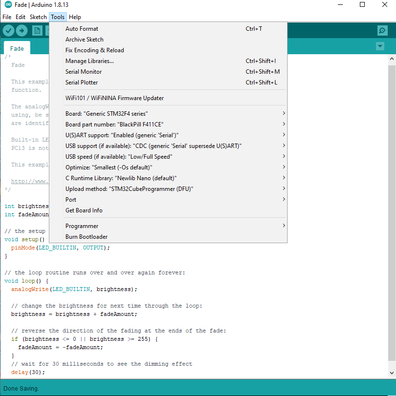
- From the Tools > Board > STM32 Board, select Generic STM32F4 series
- Select Tools > Board Part Number > BlackPill F411CE
- Under USB Support, select CDC (generic "Serial" supersede U(S)ART)
- Under Upload method, select SMT32CubeProgrammer(DFU)
- Use the onboard BOOT0 and NRST button to put the board into bootloader mode:
- press and hold the BOOT0 button
- press and release NRST (reset) button to power cycle the processor
- release BOOT0 button
- Sometimes removing the USB cable and plugging it back in while pressing BOOT0 button works better
- Upload sketch
- Displays in IDE
USB speed   : Full Speed (12MBit/s)
Manuf. ID   : STMicroelectronics
Product ID  : STM32  BOOTLOADER
SN          : 348C35983539
FW version  : 0x011a
Device ID   : 0x0431
Device name : STM32F411xC/E
Flash size  : 512 KBytes (default)
Device type : MCU
Device CPU  : Cortex-M4


Memory Programming ...
Opening and parsing file: ODASTESTER.ino.bin
  File          : ODASTESTER.ino.bin
  Size          : 49132 Bytes
  Address       : 0x08000000


Erasing memory corresponding to segment 0:
Erasing internal memory sectors [0 2]
erasing sector 0000 @: 0x08000000 done
erasing sector 0001 @: 0x08004000 done
erasing sector 0002 @: 0x08008000 done
Download in Progress:


File download complete
Time elapsed during download operation: 00:00:02.263

RUNNING Program ...
  Address:      : 0x8000000
Start operation achieved successfully
Other Programming
- ST-LINK V2
- FLASHER-STM32 - STM32 Flash loader demonstrator (UM0462)
- From AN3155

