Difference between revisions of "BBB-COMMS-2"
Jump to navigation
Jump to search
Blwikiadmin (talk | contribs) |
Blwikiadmin (talk | contribs) |
||
| Line 139: | Line 139: | ||
# VCC | # VCC | ||
# GPIO1_13 (P8_11) | # GPIO1_13 (P8_11) | ||
| + | |||
| + | == Schematics == | ||
| + | |||
| + | * [ Rev X1] | ||
| + | * [ Rev 2] | ||
== Production Testing == | == Production Testing == | ||
Revision as of 15:44, 8 April 2022
Contents
- 1 Features
- 2 Headers and Connectors
- 2.1 Header
- 2.2 Connectors
- 2.2.1 H2 - Power/Ground
- 2.2.2 H3 - GPIO3_19, GPIO1_17 Pins
- 2.2.3 H4 - UART1
- 2.2.4 H5 - UART2
- 2.2.5 H6 - I2C1
- 2.2.6 H7 - EHRPWM1A, GPIO1_28 Pins
- 2.2.7 H8 - EHRPWM1B GPIO3_19 Pins
- 2.2.8 H9 - UART4
- 2.2.9 H10 - KEY
- 2.2.10 H11 - GPIO1_29
- 2.2.11 H12 - GPIO2_1
- 2.2.12 H13 - GPIO0_27
- 2.2.13 H14 - GPIO1_14
- 2.2.14 H14 - GPIO1_14
- 2.2.15 H15 - GPIO1_15
- 2.2.16 H16 - GPIO1_12
- 2.2.17 H17 - GPIO1_13
- 3 Schematics
- 4 Production Testing
- 5 I2C Testing
- 6 Drivers / Example Code
- 7 BBB-COMMS-2 Assembly Sheet/Parts List
Features
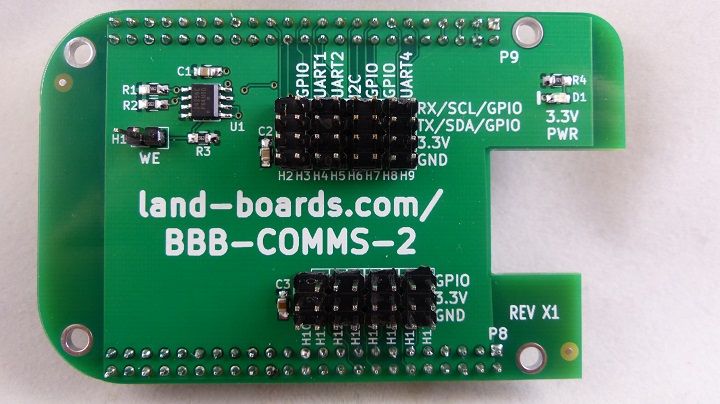
Extensive I/O connections
- (13) GPIOs - GVS (Ground/Voltage/Signal) pins
- GVS (Ground/Voltage/Signal) pins
- (3) UARTs - GVTxRx (Ground/Voltage/Tx/Rx) pins
- GVTxRx (Ground/Voltage/Tx/Rx) pins
- (1) I2C bus- GVSdaScl (Ground/Voltage/SDA/SCL) pins
- GVSdaScl (Ground/Voltage/SDA/SCL) pins
- Support for keyed headers
- Cape Support features
- Cape configuration EEPROM with write enable jumper
- On I2C2 interface
- Beaglebone Black form factor
- Power LED
Headers and Connectors
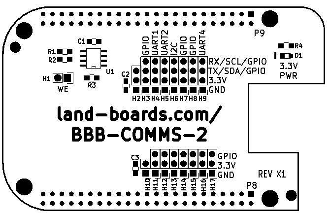
Header
H1 - Write Enable Header
- Install jumper onto header to allow writes to EEPROM
- Remove jumper from header to prevent writes to EEPROM
Connectors
H2 - Power/Ground
- GND
- VCC
- N/C (KEY)
H3 - GPIO3_19, GPIO1_17 Pins
- GND
- VCC
- GPIO3_19 (P9_27)
- GPIO1_17 (P9_23)
H4 - UART1
- GND
- VCC
- UART1_TXD (P9_24)
- UART1_RXD (P9_26)
H5 - UART2
- GND
- VCC
- UART2_TXD (P9_21)
- UART2_RXD (P9_22)
H6 - I2C1
- GND
- VCC
- I2C1_SDA (P9_18)
- I2C1_SCL (P9_17)
H7 - EHRPWM1A, GPIO1_28 Pins
- GND
- VCC
- EHRPWM1A (P9_14)
- GPIO1_28 (P9_12)
H8 - EHRPWM1B GPIO3_19 Pins
- GND
- VCC
- EHRPWM1B (P9_16)
- GPIO3_19 (P9_27)
H9 - UART4
- GND
- VCC
- UART4_TXD (P9_C13)
- UART4_RXD (P9_C11)
H10 - KEY
H11 - GPIO1_29
- GND
- VCC
- GPIO1_29 (P8_26)
H12 - GPIO2_1
- GND
- VCC
- GPIO2_1 (P8_18)
H13 - GPIO0_27
- GND
- VCC
- GPIO0_27 (P8_17)
H14 - GPIO1_14
- GND
- VCC
- GPIO1_14 (P8_16)
H14 - GPIO1_14
- GND
- VCC
- GPIO1_14 (P8_16)
H15 - GPIO1_15
- GND
- VCC
- GPIO1_15 (P8_15)
H16 - GPIO1_12
- GND
- VCC
- GPIO1_12 (P8_12)
H17 - GPIO1_13
- GND
- VCC
- GPIO1_13 (P8_11)
Schematics
- [ Rev X1]
- [ Rev 2]
Production Testing
Setup
- Install BBB-COMMS-2 on BBB
- Install shunt at H1 (Write Enable)
- Ethernet connection to BBB
- Power via 5V jack to BBB
- Verify 3.3V LED is lit
- Log in via putty
- User = root
- Password = enter
GPIO Testing
- Hook up LED-32 Card to these pins
D0 = "P8_26"
D1 = "P8_17"
D2 = "P8_15"
D3 = "P8_11"
D4 = "P9_23"
D5 = "P9_26"
D6 = "P9_22"
D7 = "P9_15"
D8 = "P9_12"
D9 = "P9_11"

D16 = "P8_18"
D17 = "P8_16"
D18 = "P8_12"
D19 = "P9_27"
D20 = "P9_24"
D21 = "P9_21"
D22 = "P9_16"
D23 = "P9_14"
D24 = "P9_13"
- Run test via:
cd ~/pyBBB/BBB-COMMS-2/blink-BBB-COMMS-2/
python blink-BBB-COMMS-2.py
EEPROM Programming
- Go to directory
- Program the EEPROM
- Verify by typing
cd ~/pyBBB/BBB-COMMS-2/mkeeprom
cat data.eeprom > /sys/bus/i2c/devices/1-0054/eeprom
cat /sys/bus/i2c/devices/1-0054/eeprom | hexdump -C
- Result should be like -
00000000  aa 55 33 ee 41 30 42 42  42 2d 47 56 53 2d 33 00  |.U3.A0BBB-COMMS-|
00000010  00 00 00 00 00 00 00 00  00 00 00 00 00 00 00 00  |2...............|
00000020  00 00 00 00 00 00 58 31  00 00 4c 61 6e 64 20 42  |......X1..Land B|
00000030  6f 61 72 64 73 2c 20 4c  4c 43 42 42 42 2d 47 56  |oards, LLCBBB-CO|
00000040  53 2d 33 00 00 00 00 00  00 00 00 00 30 30 30 30  |MS-2........0000|
00000050  00 00 00 00 00 00 00 00  00 00 00 00 00 00 00 00  |................|
*
000000e0  00 00 00 00 00 00 00 00  00 00 00 00 00 fa 01 f4  |................|
000000f0  00 fa 00 00 ff ff ff ff  ff ff ff ff ff ff ff ff  |................|
00000100  ff ff ff ff ff ff ff ff  ff ff ff ff ff ff ff ff  |................|
*
00008000
- Remove WE jumper
- Type
cat data.eeprom > /sys/bus/i2c/devices/1-0054/eeprom
- Result should be error
root@BBB01:~/pyBBB/BBB-COMMS-2/mkeeprom# cat data.eeprom > /sys/bus/i2c/devices/1-0054/eeprom
cat: write error: Connection timed out
- Prepare to re-run
- Type
halt
- Combined Copy/Paste
cd ~/pyBBB/BBB-COMMS-2/blink-BBB-COMMS-2
python blink-BBB-COMMS-2.py

cd ~/pyBBB/BBB-COMMS-2/mkeeprom/
cat data.eeprom > /sys/bus/i2c/devices/1-0054/eeprom
cat /sys/bus/i2c/devices/1-0054/eeprom | hexdump -C
I2C Testing
Hardware
- UUT
- I2CIO-8
Enable I2C Bus
- How-To enable the I2C devices on the BeagleBone Black Rev C
- Physically connected to I2C1 port on the BBB-COMMS-2 card but is I2C-2 from the software
- Probe I2C bus 2
i2cdetect -y -r 2
- Card shows up at 0x20
root@beaglebone:~/BBB/MCP23008# i2cdetect -y -r 2
     0  1  2  3  4  5  6  7  8  9  a  b  c  d  e  f
00:          -- -- -- -- -- -- -- -- -- -- -- -- --
10: -- -- -- -- -- -- -- -- -- -- -- -- -- -- -- --
20: 20 -- -- -- -- -- -- -- -- -- -- -- -- -- -- --
30: -- -- -- -- -- -- -- -- -- -- -- -- -- -- -- --
40: -- -- -- -- -- -- -- -- -- -- -- -- -- -- -- --
50: -- -- -- -- -- -- -- -- -- -- -- -- -- -- -- --
60: -- -- -- -- -- -- -- -- -- -- -- -- -- -- -- --
70: -- -- -- -- -- -- -- --
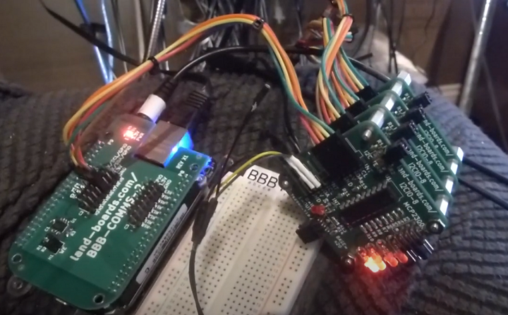
4 of I2CIO-8 cards
- Connect 4 of I2CIO-8
- I2C daisy-chain
- Address jumpers set for 0x20-0x23
- Enter
i2cdetect -y -r 2
- Result shows cards at 0x20-0x23
     0  1  2  3  4  5  6  7  8  9  a  b  c  d  e  f
00:          -- -- -- -- -- -- -- -- -- -- -- -- --
10: -- -- -- -- -- -- -- -- -- -- -- -- -- -- -- --
20: 20 21 22 23 -- -- -- -- -- -- -- -- -- -- -- --
30: -- -- -- -- -- -- -- -- -- -- -- -- -- -- -- --
40: -- -- -- -- -- -- -- -- -- -- -- -- -- -- -- --
50: -- -- -- -- -- -- -- -- -- -- -- -- -- -- -- --
60: -- -- -- -- -- -- -- -- -- -- -- -- -- -- -- --
70: -- -- -- -- -- -- -- --
Run Example Code
cd /root/BBB/MCP23008
root@beaglebone:~/BBB/MCP23008# ls -al
total 12
drwxr-xr-x  2 root root 4096 Apr 23  2014 .
drwxr-xr-x 17 root root 4096 Apr 23  2014 ..
-rwxr-xr-x  1 root root 1508 Apr 24  2014 MCP23008_ex.py
- Run using
python MCP23008_ex.py
I2C Timing
- 100 KHz


