Difference between revisions of "I2CIO-8"
Jump to navigation
Jump to search
Blwikiadmin (talk | contribs) |
Blwikiadmin (talk | contribs) |
||
| Line 228: | Line 228: | ||
=== QT Py Python Example === | === QT Py Python Example === | ||
| − | * [https://github.com/land-boards/lb-boards/blob/master/Projects/QTPy/Land%20Boards/Land%20Boards%20QT%20Py%20Code/I2CIO8.py I2CIO8.py Demo code] | + | * [https://github.com/land-boards/lb-boards/blob/master/Projects/QTPy/Land%20Boards/Land%20Boards%20QT%20Py%20Code/I2CIO8.py I2CIO8.py Demo code] - Alternating pattern |
| + | * [https://github.com/land-boards/lb-boards/blob/master/Projects/QTPy/Land%20Boards/Land%20Boards%20QT%20Py%20Code/I2CIO8_RW.py I2CIO8_RW.py] _ Read jumpers, write back LEDs | ||
=== Raspberry Pi Pico === | === Raspberry Pi Pico === | ||
Revision as of 19:42, 1 June 2022
Contents
Features
- 8 bits of Digital I/O
- I2C interface
- MCP23008 - 8-Bit I/O Expander with I2C Interface
- Base address = 0x20
- Address offset jumpers (0-7)
- Interrupt pin on I2C connectors
- Interrupt LED
- I2C Daisy-chain connectors
- 4 input (or output) jumpers
- 4 LEDs
- 2.7V to 5.5V
- 49x49mm form factor
- (4) #4-40 mounting holes
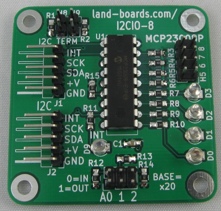
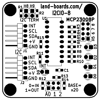
Headers/Jumpers - Rev X1, X2 Board
J1, J2 - I2C Connectors
- Daisy-chain connectors
- Can ignore second connector
- Pinout
- GND
- Power (2.7V-5V)
- SDA
- SCL
- Interrupt (Out)
H5-H8 - GVS connectors
- D4-D7
- Signal/Ground
H8, H9 - I2C Terminators
- Install to terminate SDA/SCL with 2.2K terminator
A0-A2 - I2C Address Jumpers
- Install all 3 for address - 0x20
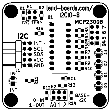
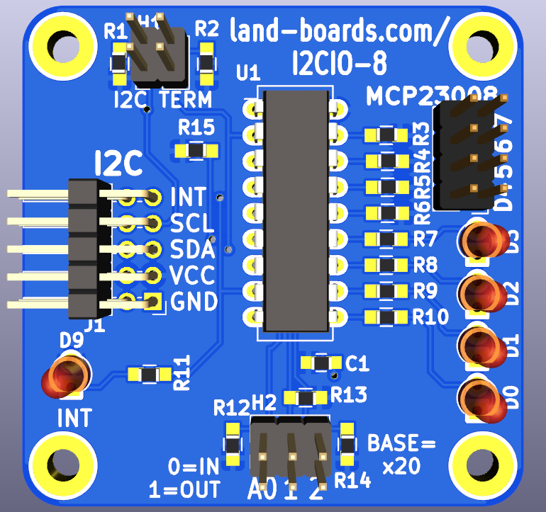
Headers/Jumpers - Rev 3
J1 - I2C Connector
- Daisy-chain connectors
- Duplicated all 5 pins
- Right angle 0.1" pitch header
- Can ignore second side of connector is not daisy-chaining other cards
- Pinout
- GND
- Power (3.3V or 5V)
- SDA
- SCL
- Interrupt (Active-Low Output)
H1 - I2C Terminators
- Install shunts to terminate SDA/SCL with 2.2K terminators
H2 - I2C Address Jumpers
- Install all 3 shunts for address - 0x20
H3 - D4-D7 Inputs Header
- D4-D7
- Signal/Ground
- 10K Pullups
Indicators
D0-D3 LEDS
- D0-D3 outputs
D9 - INT LED
- Interrupt - LED goes off when interrupt is present (Rev X1, X2 cards)
- Interrupt - LED goes on when interrupt is present (Rev 3 card)
Schematics
Factory Acceptance Test
Test Station Theory of Operations
- Test Station controls the I2C interface on the UUT
- Three tests
- Internal Test
- External Loopback Test
- Bounce an LED Test
Test Station Set-up
- Uses ODAS Test Station V2
- Unit Under Test (UUT)
- Attach Host Computer USB to the Arduino NANO on the Test Station
- Run puTTY on the Host Computer
- 9600 baud
Card Selection
- puTTY will display the menu
Checking if EEPROM is present on UUT...EEPROM is not present on UUT
Count of I2C devices in range 0x20-0x27 on UUT = 1
Detected MCP23008
Select the board type (Other)
1 - I2CIO8 board
2 - I2CIO8X board
Select board >
- Select 1
Init I2CIO-8 card
C=Card Tests, D=Direct, E=EEPROM, I=access Internal DIGIO32
Running Card Test
- Select Card Tests = "C"
- Select Run Tests = "T"
- Move jumper across the 4 jumper pins H5-H8
- LEDs will correspond
- INT LED will blink on/off
- Observe test results
C=Card Tests, D=Direct, E=EEPROM, I=access Internal DIGIO32
L=Loop/S=Single, T=Test, B=Bounce LEDs, I=UUT Int'l Tests, X=eXit sub-menu
Testing UUT = I2CIO-8
I2CIO8 card tests
Move jumper across H5-H8, observe LEDs D0-D3
Verify Int LED blinks
Hit a key to stop test
Test PASS = 1, FAIL = 0
- Hit ENTER to display menu
L=Loop/S=Single, T=Test, B=Bounce LEDs, I=UUT Int'l Test, X=eXit sub-menu
Running Internal Tests
- Remove loopback cable
- Select Card Tests = "C"
- Select Run Tests = "I"
- Observe test results
L=Loop/S=Single, T=Test, B=Bounce LEDs, I=UUT Int'l Tests, X=eXit sub-menu
UUT Internal card tests
Test PASS = 2, FAIL = 0
- Hit ENTER to display menu
L=Loop/S=Single, T=Test, B=Bounce LEDs, I=UUT Int'l Test, X=eXit sub-menu
Running Blink LED Test
- Select Card Tests = "C"
- Select Run Tests = "B"
- Observe LEDs scanning on the 4 LEDs on the card
L=Loop/S=Single, T=Test, B=Bounce LEDs, I=UUT Int'l Test, X=eXit sub-menu
Bounce a bit across outputs
Bouncing LEDs I2CIO8 - any key to stop
- Hit ENTER to display the menu
Finished bouncing LEDs
Reference
Drivers/Example Code
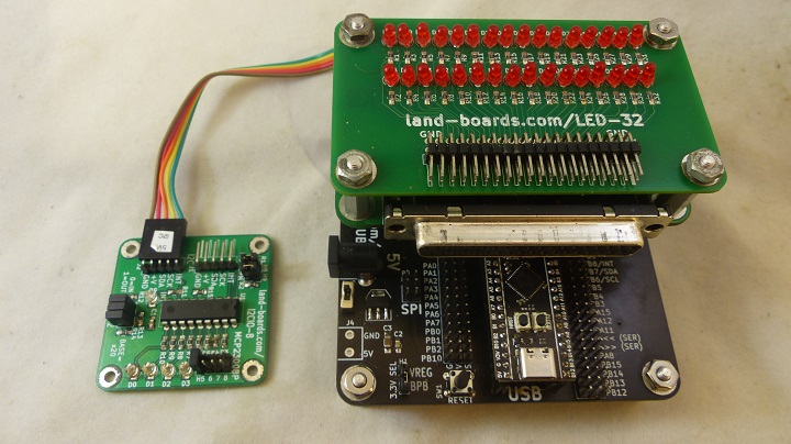
Extensive Driver Support for Arduino, Raspberry Pi, MicroPython, ESP-32, Blue Pill Board, Cypress PSoC
Arduino Driver / Examples
- LandBoards_I2CIO8 Arduino Driver code - GitHub repo
- Example code - GitHub repo
BeagleBone Black
ESP32
- Github repo - MicroPython Driver
PSOC5 Driver
Raspberry Pi Example
QT Py Python Example
- I2CIO8.py Demo code - Alternating pattern
- I2CIO8_RW.py _ Read jumpers, write back LEDs
Raspberry Pi Pico
MMBASIC
Changes
Rev 3
- Change I2C to 2x5 right angle header
- INT trace on rear side so it could be cut to isolate 2nd daisy-chain
- Combine I2C terminator headers into one 2x2 header
- Re-label GP4-7 inputs as D4-7
- Add 3D parts to model
- Flip polarity on INT LED so it lights when interrupt was present
- Move INT LED closer to board edge
- Rotate LEDS so they can be mounted at a right angle
- Allows close stacking of cards

