Difference between revisions of "USB-GPS"
Jump to navigation
Jump to search
Blwikiadmin (talk | contribs) (Created page with "File:USB-GPS-P686-720px.jpg == USB-GPS Features == <pre> Minimal design No battery draining display Indicators 2 Programmable LEDs For instance, LED can be programmed to...") |
Blwikiadmin (talk | contribs) |
||
| Line 69: | Line 69: | ||
DS1 Microprocessor PB2 output pin | DS1 Microprocessor PB2 output pin | ||
DS3 Microprocessor PB1 output pin | DS3 Microprocessor PB1 output pin | ||
| − | <pre> | + | </pre> |
== Part Selection == | == Part Selection == | ||
Revision as of 16:27, 10 January 2020
Contents
USB-GPS Features
Minimal design
No battery draining display
Indicators
2 Programmable LEDs
For instance, LED can be programmed to reflect the GPS lock signal
Can be programmed to not go on for "stealth" applications
Charge in progress (red)/charge complete (green) LED
MT3339 GPS - Capable of Data logging up to 16 hours at 32 seconds per log entry
ATMega32U4, 8-bit Microprocessor
Built-in USB interface
Doesn't require FTDI friend or other USB to TTL interface
Mini-USB-B jack
Information about USB connectors
Used for battery charging and Host Communication
Li-Polymer battery charger
Charges from USB
JST connector for direct battery connection
Compatible with Li-Poly Batteries
Extended voltage operation from 4.2V down to 3.0V of Li-Poly batteries
Works with Adafruit 1300 mA-hr Li-Poly battery
Battery form factor of battery is 1.35" x 2.55" x 0.23"
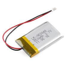
Works with Sparkfun 850 mA-hr battery
Form factor of 1.16" x 1.9" x 0.23"
Measured 35 mA current draw
Allows for 36+ hr battery life with 1300 ma-hr battery or 24+ hours with the 850 ma-hr battery
Well beyond the 32 hour log time of the GPS (in 15 second mode)
Battery life could be extended while logging by putting the AVR into sleep mode (20-25 mA for GPS only)
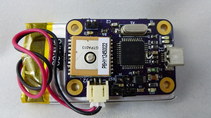
Very Small form factor
1.79x1.27 inch
Design goal was to make the device and battery small enough to fit into an Tic Tac candy dispenser
Connectors
J1 - USB, Mini-B
Standard USB Mini-B pinout.
J2 - JST connector for Li-Poly battery
J3 - Power Switch
The power switch has a two pin header. When the pins are connected the power is applied from the battery to the rest of the card.
J4 - Reset
Reset has a two pin header. To reset the Microprocessor temporarily short the two pins. To enter programming mode, the HWB jumper should be installed prior to activating the reset.
J5 - HWB
HWB is used for programming the Microprocessor.
Pin	Description
1	HWB (pulled up tp +5V)
2	Ground
Install shunt from 1-2 to allow board to go into programming mode (also requires cycling the reset line to the Microprocessor.
SW1 - Input switch for control
Indicators
Indicator	Function
DS2	On = USB power is good
DS1	Microprocessor PB2 output pin
DS3	Microprocessor PB1 output pin
Part Selection
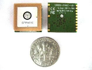
GPS selection - MTK3339
Low Cost ($30) MTK3339 GPS part from Adafruit
-165 dBm sensitivity, 10 Hz updates, 66 channels
Ultra low power usage: 20mA current draw while tracking, 25mA acquisition
Power Supply, VCC: 3.0V to 4.3V, (VBACKUP: 2.0V to 4.3V not used)
RTC battery-compatible (LiPoly battery connects to this)
Built-in "LOCUS" datalogging (up to 16 hours)
PPS output on fix
Tested at 27 Km altitude
Internal patch antenna + connection for optional external active antenna
Fix status output
Ultra small size: only 16mm x 16mm x 5mm and 4 grams
Frequency L1, 1575.42MHz
Sensitivity1 Acquisition: -148dBm, cold start, Reacquisition: -163dBm, Hot start
Tracking: -165dBm
Channel 66 channels
TTFF Hot start: 1 second typical, Warm start: 33 seconds typical, Cold start: 35 seconds typical
(No. of SVs>4, C/N>40dB, PDop<1.5)
Without aid:3.0m (50% CEP)
DGPS (SBAS(WAAS,EGNOS,MSAS)):2.5m (50% CEP)
Position Accuracy
Velocity Accuracy Without aid : 0.1m/s
DGPS (SBAS(WAAS,EGNOS,MSAS,GAGAN)):0.05m/s
Without aid:0.1 m/s2
Acceleration Accuracy Without aid:0.1 m/
DGPS (SBAS(WAAS,EGNOS,MSAS)):0.05m/s2
Timing Accuracy 10 ns RMS
(1PPS Output)
Altitude Maximum 18,000m (60,000 feet)
Velocity Maximum 515m/s (1000 knots)
Acceleration Maximum 4G
Update Rate 1Hz (default), maximum 10Hz
Baud Rate 9600 bps (default)
DGPS SBAS (defult) [QZSS,WAAS, EGNOS, MSAS,GAGAN]
AGPS Support
Working Temperature -40 °C to +85 °C
Dimension 16 x 16 x 6.2mm, SMD
Weight 6g
Battery Selection - 3.7V Li-Poly
Rechargeable - Many choices of mA-hr capacities
Slow self discharge rate - LiPo best fit
GPS stores up to 16 hours of breadcrumbs.
GPS uses 20 mA when in sync
Arduino can go into sleep mode using 0 mA
16 hrs x 22 mA / hr = 32;
0 mAh
ID AdaFruit part - : 258 has features:
Cost $10
Weight: 25g
Size: 1.35" x 2.55" x 0.23" (35mm x 65mm x 5.5mm)
Size means part won't fit into a small Altoids' tin.
Output: 1300mAh at 3.7V nominal
1300 mAhr / 20 mA = 65 hrs (2+ days)
Sparkfun part has features:
Cost $9
860 mAhr
1.16" x 1.9" x 0.23"
Charger Selection - MCP73833
Charges Lithium Polymer batteries from USB power (+5V at 500 mA)
Charges in < 3 hrs
Enclosures - Candy
Enclosure Ideas
Drivers/Software
KML output for use with Google Earth
Arduino development environment compatible
GPS data logger application
USB GPS Software repository
LUFA Serial
USB to Serial working]
Adafruit driver for MTK3339
GPS datalogger
Revision X2 Improvements over the X1 board
NTC resistor pads 0603 to match available parts (X1 had 0805 pads)
Added reset header holes to make firmware development easier
Moved resistor near JST power connector to make it easier to move JST in
Move around parts near LiPoly charger to make more room
Eliminated the connections from the LiPoly charger to the Microprocessor so to eliminate backpowering the charger from the Microprocessor
Changed the LED associated with the charger from indicating that there is +5V to the PG (power good) output of the charger
Battery connected directly to the GPS VBATT power connection to keep the GPS in low-power mode when shut off
Revision X1 Board
File:Usb-gps-x1 scan scaled.png
Connectors (Rev X1)
J1 - USB, Mini-B
Standard USB Mini-B pinout.

J2 - JST connector for Li-Poly battery
Standard JST connector mates to the JST connector at the end of the battery wires.

J3 - Power Switch
The power switch has a two pin header. When the pins are connected the power is applied from the battery to the rest of the card.

SJ1 - HWB
Revision X1 - Issues
- Vbackup on GPS should connect directly to VBATT so that when the power switch is off, the GPS still retains the settings
( GPS Rev X1 Hardware Bring-up Notes


