Difference between revisions of "UNI-OPAMP-04"
Jump to navigation
Jump to search
Blwikiadmin (talk | contribs) |
Blwikiadmin (talk | contribs) |
||
| Line 1: | Line 1: | ||
[[File:tindie-mediums.png|link=https://www.tindie.com/products/land_boards/universal-op-amp-card-uni-opamp-08/]] | [[File:tindie-mediums.png|link=https://www.tindie.com/products/land_boards/universal-op-amp-card-uni-opamp-08/]] | ||
| + | |||
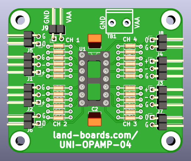
| + | [[File:UNI-OPAMP-04_FRONT_3D.png]] | ||
== Four Channel Universal Op Amp == | == Four Channel Universal Op Amp == | ||
| − | |||
| − | |||
== Features == | == Features == | ||
Revision as of 11:37, 26 July 2022
Contents
Four Channel Universal Op Amp
Features
- Universal OpAmp Board
- Configurable for typical OpAmp circuits
- 4 Channels
- 1 Quad OpAmp
- Individual input and output headers per channel
- Terminal block for power
- Bypass capacitors
- 59X49mm form factor
- (4) 4-40 mounting holes
Connectors
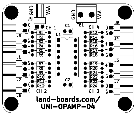
J1-J4 - Inputs
J5-J8 - Outputs
Configurations
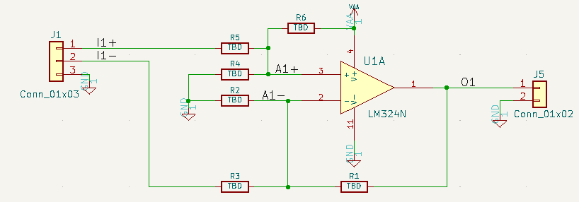
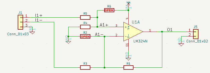
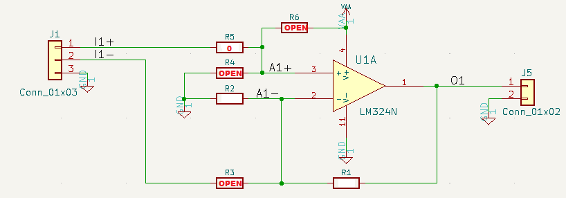
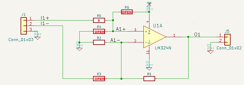
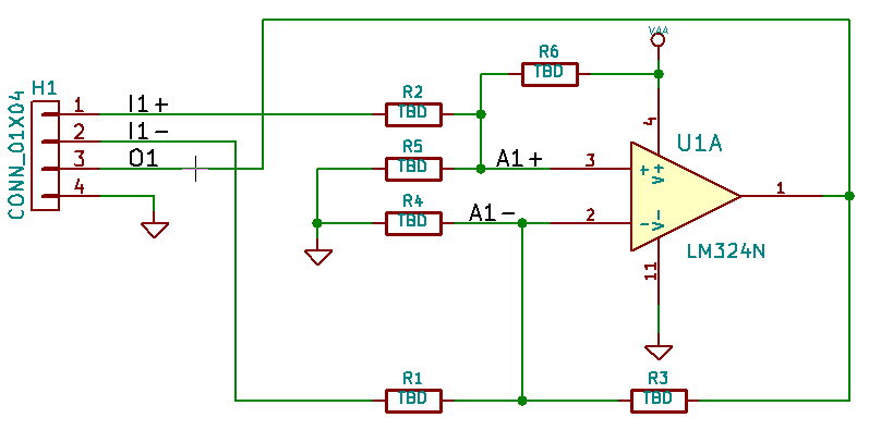
- The reference designs (below) are for the first channel.
- The resistor mapping from the first channel on the schematic to the other channels are as follows.
Resistors
| OpAmp | Ax-/Ix- | Ax+/Ix+ | Ax-/Qx | Ax-/Gnd | Ax+/Gnd |
|---|---|---|---|---|---|
| U1A | R1 | R2 | R3 | R4 | R5 |
| U1B | R6 | R7 | R8 | R10 | R9 |
| U1C | R11 | R12 | R13 | R14 | R15 |
| U1D | R16 | R17 | R18 | R20 | R19 |
| U2A | R23 | R24 | R25 | R21 | R22 |
| U2B | R28 | R29 | R30 | R27 | R26 |
| U2C | R33 | R34 | R35 | R31 | R32 |
| U2D | R38 | R39 | R40 | R37 | R36 |
Reference Designs
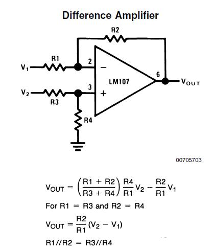
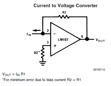
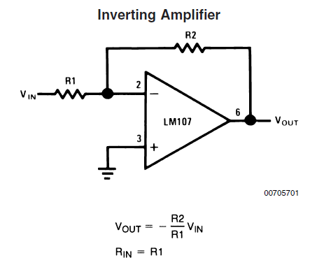
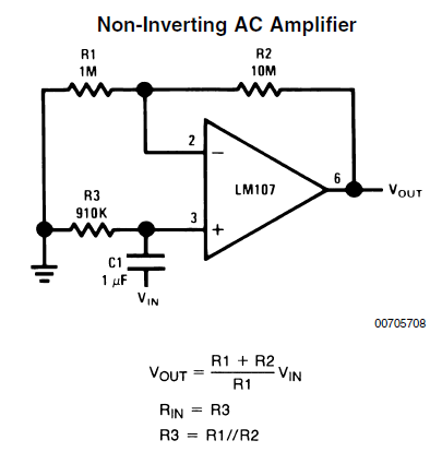
- Reference drawings are from Ap Note 31
- Reference designators are for channel 1
- See resistor values table (above) schematic for other channels

