Difference between revisions of "QTPy49"
Jump to navigation
Jump to search
Blwikiadmin (talk | contribs) |
Blwikiadmin (talk | contribs) |
||
| Line 136: | Line 136: | ||
* Digital I/O 3 | * Digital I/O 3 | ||
* Analog In 3 | * Analog In 3 | ||
| + | * GP29 on XIAO-RP2040 | ||
| + | * PA05 on Adafruit SAMD21 | ||
* PWM output | * PWM output | ||
* Capacitive touch input | * Capacitive touch input | ||
Revision as of 11:25, 12 August 2022
Contents
Features
- CPU choices are
- QT Py (SAMD based)
- QT Py (RP2040 based)
- XIAO ESP32C3
- SeeedStudio XIAO ESP32C3 (New 2022-07)
- RISC-V Single Core
- Up to 160 MHz
- 400 KB SRAM
- 4 MB Flash
- 2.4GHz Wi-Fi subsystem
- Wiki
- ESP32C3 Datasheet
- Connectors/Headers
- DC Power
- AD0 GVS
- AD1 GVS
- AD2 GVS
- AD3 GVS
- I2C with ground/VCC
- TX/RX with ground/VCC
- SPI with ground/VCC
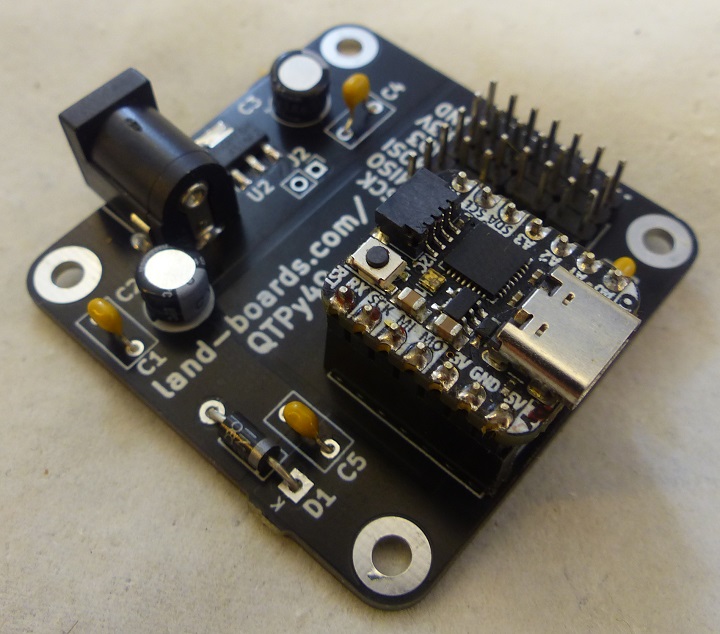
- QTPy49 can be powered from with either the USB C or DC jack
- Automatic Schottky diode power switching between
- 5V from USB C
- 5V on external DC jack
- 7-12V on DC jack
- Automatic Schottky diode power switching between
- 49x49mm ODAS form factor
- (4) 4-40 mounting holes
CPU Pinouts
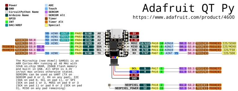
Adafruit QT Py SAMD
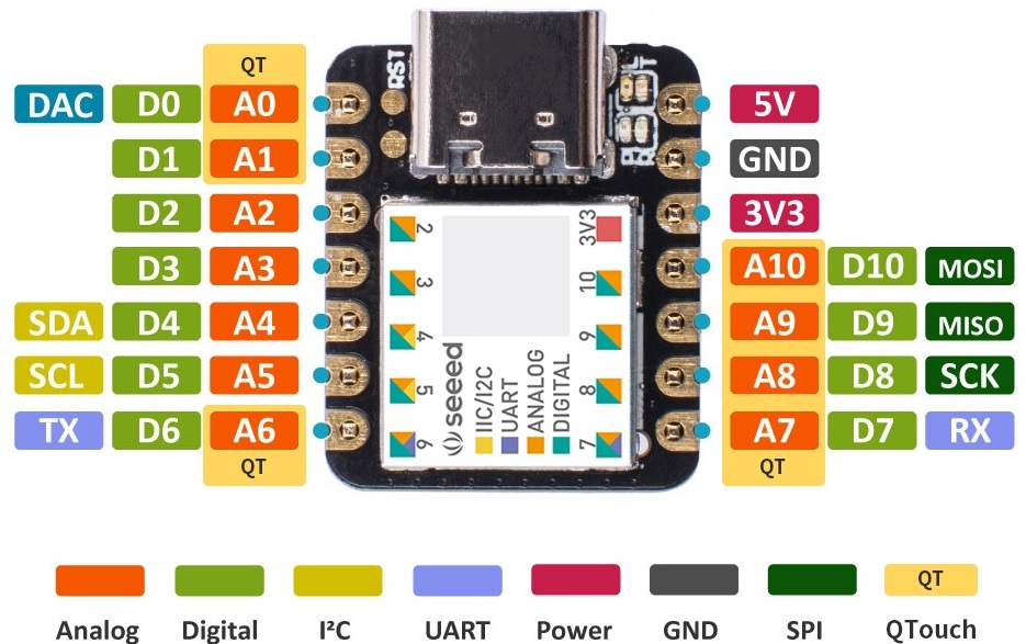
Seeed Studio XAIO SAMD
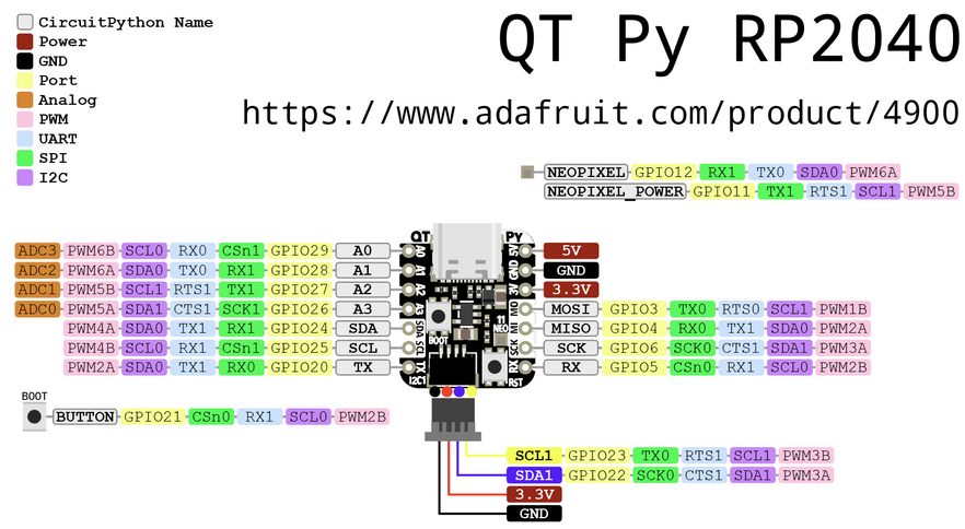
Adafruit QT Py RP2040
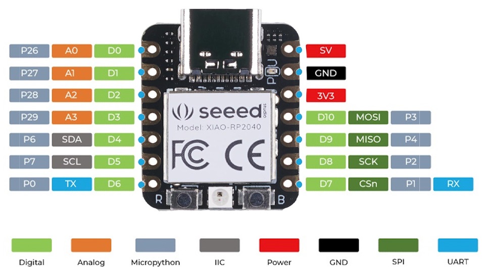
Seeed Studio XAIO RP2040
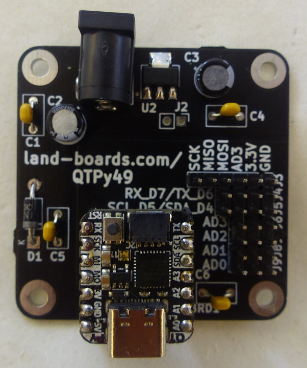
Connectors/Headers
- Ground, Voltage, Signal (GVS) connections
J1 - DC In
- QTPy49 can be powered from either the USB C or DC jack
- Automatic Schottky diode power switching
- Can use a regular Silicon Diode with sufficient current ex: 1N400X)
- 7-12V if regulator is installed
- 5V if regulator is not installed (install J2 jumper if not using regulator)
- Automatic Schottky diode power switching
- Center positive
J2 - Short Regulator
- Install if J1 has 5V
- No need to install U2 regulator
J3 - SPI
- GND
- 3.3V
- SS, AD3 (wired to J6-3)
- MOSI, S10
- MISO, D9
- SCK, D8
J3 - SD Card
- MISO - AD9
- GP4 on XIAO-RP2040
- PA09 on Adafruit SAMD21
- MOSI - AD10
- GP3 on XIAO-RP2040
- PA10 on Adafruit SAMD21
- SCK - AD8
- GP2 on XIAO-RP2040
- PA11 on Adafruit SAMD21
- SS - AD0
- GP26 on XIAO-RP2040
- PA02 on Adafruit SAMD21
J4 - UART
- GND
- 3.3V
- TX, D6
- RX, D7
- D6
- GP0 on XIAO-RP2040
- PA06 on Adafruit SAMD21
- D7
- GP1 on XIAO-RP2040
- PA07 on Adafruit SAMD21
J5 - I2C
- GND
- 3.3V
- D4, SDA
- D5, SCL
- D4
- GP6 on XIAO-RP2040
- PA16 on Adafruit SAMD21
- D5
- GP7 on XIAO-RP2040
- PA17 on Adafruit SAMD21
J6 - AD3
- Digital I/O 3
- Analog In 3
- GP29 on XIAO-RP2040
- PA05 on Adafruit SAMD21
- PWM output
- Capacitive touch input
- Pinout
- GND
- 3.3V
- AD3 (wired to J3-3)
J7 - AD2
- Digital I/O 2
- Analog In 2
- PWM
- Capacitive touch input
- Pinout
- GND
- 3.3V
- AD2
J8 - AD1
- Digital I/O 1
- Analog In 1
- Capacitive touch input
- AREF pin
- Pinout
- GND
- 3.3V
- AD1
J9 - AD0
- Digital I/O 0
- Analog In 0
- True analog output with 10 bit precision
- Does not have PWM
- Capacitive touch input
- Pinout
- GND
- 3.3V
- AD0
Applications
Sample applications for the QTPy49 card.
SD Card Loader
GPS frequency Standard
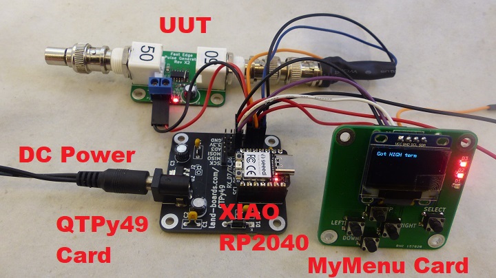
Pulse Generator Test Station
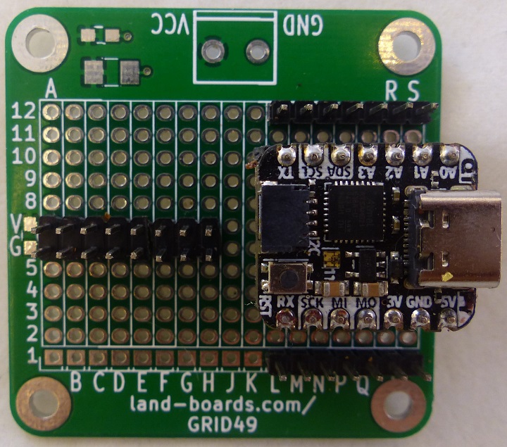
Prototype
- Built on GRID49 card
- Breaks out QY Py pins to (2) 1x7 headers
- Power/ground distribution on 2x8 header
- Limit: Must be powered from USB C connector

