Difference between revisions of "MIDI-IN-OUT"
Jump to navigation
Jump to search
Blwikiadmin (talk | contribs) |
Blwikiadmin (talk | contribs) |
||
| Line 14: | Line 14: | ||
=== J1 - MIDI In === | === J1 - MIDI In === | ||
| + | |||
| + | [[FILE:MIDI_IN_SCHEMATIC.PNG]] | ||
* Opto-isolated input | * Opto-isolated input | ||
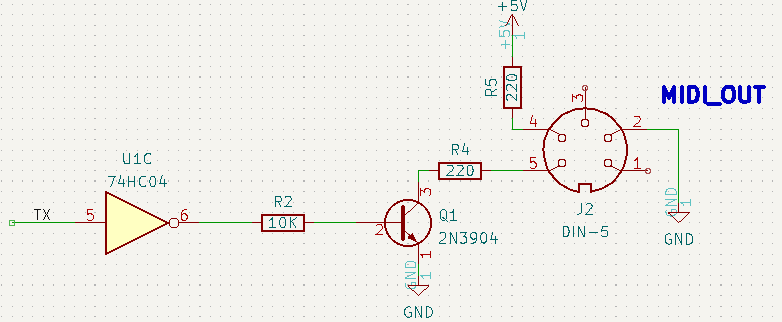
=== J2 - MIDI Out === | === J2 - MIDI Out === | ||
| + | |||
| + | [[FILE:MIDI_OUT_SCHEMATIC.PNG]] | ||
=== J3 - Serial/Power === | === J3 - Serial/Power === | ||
Revision as of 08:29, 25 September 2022
Contents
Features
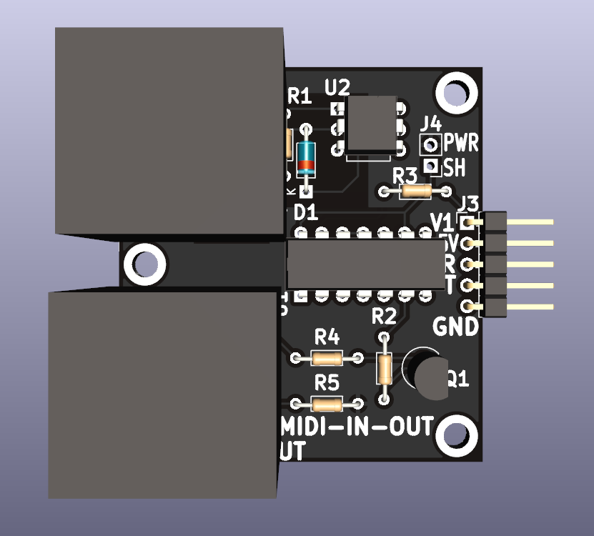
- Module for Prototyping Synthesizer components
- MIDI In/Out Jacks
- Opto-isolated MIDI Input
- 5V MIDI interface
- 3.3V or 5V Serial connections
- MIDI In is opto-isolated
- (2) 4-40 Mounting holes
Connectors
J1 - MIDI In
- Opto-isolated input
J2 - MIDI Out
J3 - Serial/Power
- Pinout
- V1 (3.3V or 5V
- 5V
- Receive data (out of card)
- Transmit (in to card)
- GND
J4 - Short V1 to 5V
- Short J3-1 to J3-2
- Used when Host is 5V


