Difference between revisions of "ER-MIDI-CV4-02"
Jump to navigation
Jump to search
Blwikiadmin (talk | contribs) |
Blwikiadmin (talk | contribs) |
||
| Line 4: | Line 4: | ||
* Eurorack 6HP, 3U module | * Eurorack 6HP, 3U module | ||
| − | |||
| − | |||
| − | |||
| − | |||
| − | |||
* Three card stack-up | * Three card stack-up | ||
** Front Panel card | ** Front Panel card | ||
| Line 28: | Line 23: | ||
* CLK output (0-5V) | * CLK output (0-5V) | ||
* Standard Eurorack 16 pin power header | * Standard Eurorack 16 pin power header | ||
| + | |||
| + | === Credits === | ||
| + | |||
| + | * Adapted from [https://note.com/solder_state/n/n17e028497eba HAGIWO's MIDI to CV module] | ||
| + | ** Translate from Japanese to English using browser | ||
| + | ** Has 4 Analog Outputs instead of 2 | ||
| + | ** Arduino Pro Mini instead of Arduino NANO | ||
| + | * Based also on [[SYNTH-MIDI-CTL-01]] | ||
=== Arduino Pins === | === Arduino Pins === | ||
Revision as of 14:37, 12 November 2022
Features
- Eurorack 6HP, 3U module
- Three card stack-up
- Front Panel card
- Controls card
- 8 jacks, 1 pot
- Processor card
- Arduino Pro Mini
- 16 MHz
- 5V
- MIDI In
- TRS Type A jack MIDI In
- USB MIDI In if external FTDI card/cable
- (4) 0-5V Analog CV outs
- MCP4822 12-bit D/A - SPI Interface
- D/A has built in output opamps, set gain to 2X
- Outputs may only swing 2x 2.048V or 4.096V (4 octaves)
- GATE output (0-5V)
- CLK output (0-5V)
- Standard Eurorack 16 pin power header
Credits
- Adapted from HAGIWO's MIDI to CV module
- Translate from Japanese to English using browser
- Has 4 Analog Outputs instead of 2
- Arduino Pro Mini instead of Arduino NANO
- Based also on SYNTH-MIDI-CTL-01
Arduino Pins
- Arduino Pro Mini
- Analog 1 - Speed Adjust POT
- A4 = SDA
- A5 = SCL
- D8 = LDAC1* to CV_1, CV2
- D9 = LDAC2* to CV_3, CV_4
- D13 = SPI CSK to both ADCs
- D11 = SPI MOSI to both ADCs
- D10 = SLAVE SELECT to both ADCs
Connectors
- As referenced from Processing card
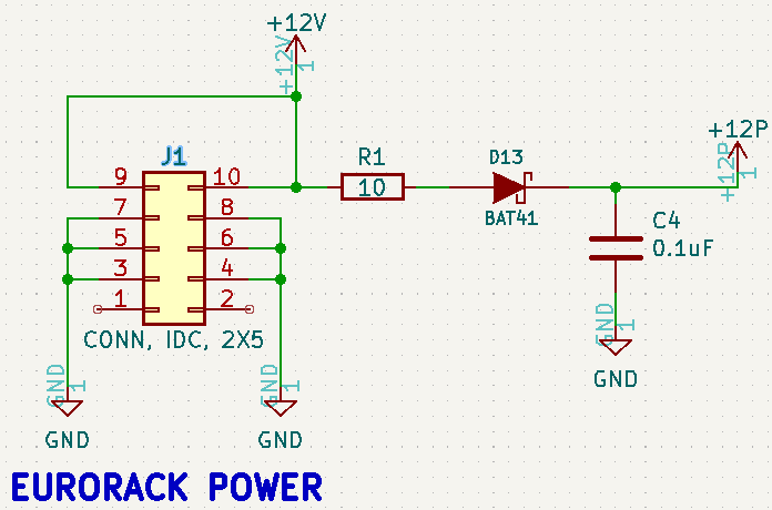
J1 - Eurorack Power
- 2x5 IDC connector
- Only uses +12V (and GND)
- Diode polarity protected, series resistor
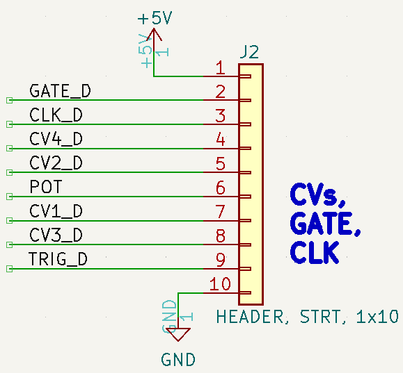
J2 - CVs, GATE, CLK (to/from Controls card)
- J12 on Controls card
- Pinout
- VCC (+5V)
- GATE
- CLK
- CV4
- CV2
- POT
- CV1
- CV3
- TRIGGER
- GND
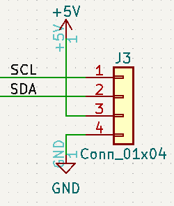
J3 - I2C
- Pinout
- SCL
- SDA
- VCC (+5V)
- GND
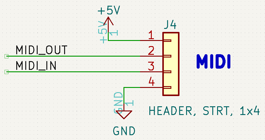
J4 - MIDI (to/from Controls card)
- J9 on Controls card
- Pinout
- VCC (+5V)
- MIDI Out
- MIDI In
- GND
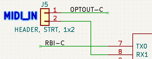
J5 - MIDI into RX
- Remove to use MIDI from Controls card
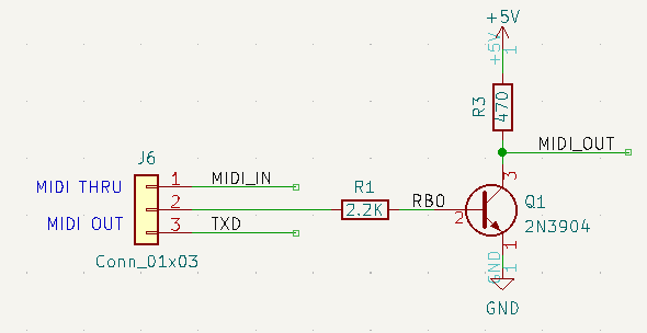
J6 - MIDI OUT/THRU Select
- 1-2 = MIDI Thru
- 2-3 = MIDI out from Arduino TX
Application
- Use with ER-VCO-03 to control pitch and Mod
- CV_1 = V/OCT
- CV_2 = MOD
- Use with ER-VCA2-01 to control amplitude
HAGIWO code baseline
- SYNTHMIDICTL01.ino
- Runs on Arduino NANO
- Used as baseline and converted to CircuitPython
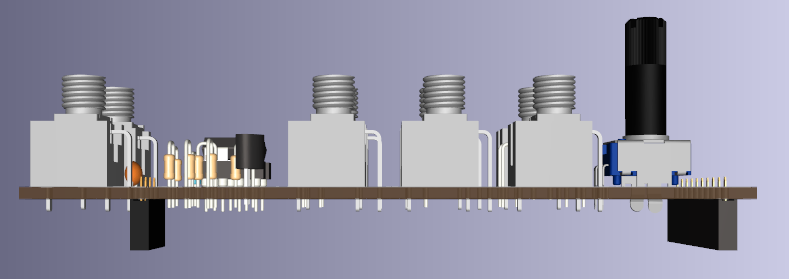
3D Views
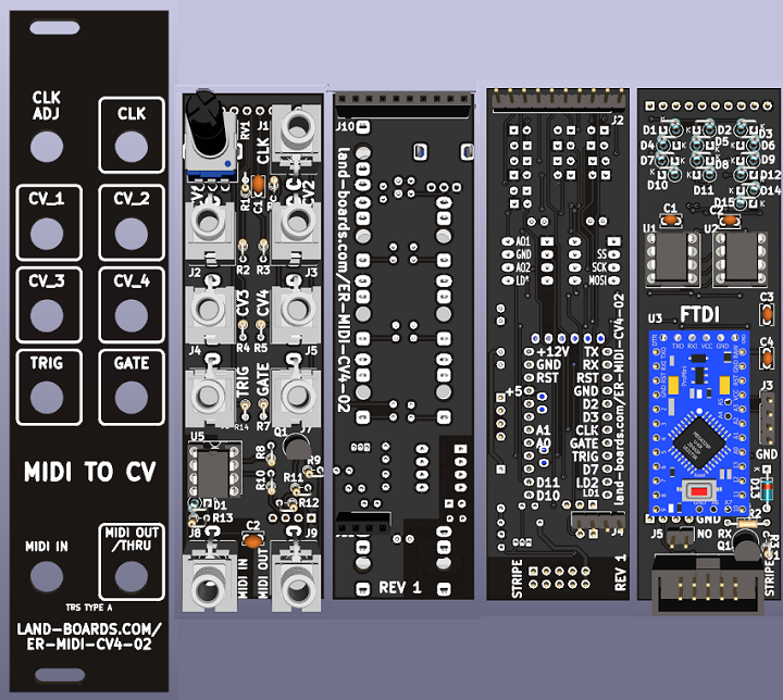
- Controls card side view
- Processing card side view
Videos
- HAGIWO MIDI to CV module
- Midi2CV - A utility module for converting MIDI messages to CV] Benjie Jiao - DIY Modular Synth Project_
