Difference between revisions of "ER-USB-MIDI"
Jump to navigation
Jump to search
Blwikiadmin (talk | contribs) |
Blwikiadmin (talk | contribs) |
||
| Line 9: | Line 9: | ||
* J6 = MIDI Serial output | * J6 = MIDI Serial output | ||
* J5 = MIDI Serial input (future feature) | * J5 = MIDI Serial input (future feature) | ||
| + | |||
| + | === Resources === | ||
| + | |||
| + | * [https://minimidi.world/ A simplified guide to TRS MIDI] | ||
== Seeeduino XIAO RP2040 == | == Seeeduino XIAO RP2040 == | ||
Revision as of 07:35, 16 January 2023
Contents
Features
- USB MIDI to MIDI Serial
- MIDI In/Out
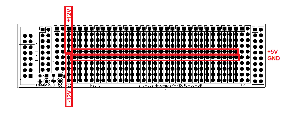
- Built on ER-PROTO-02
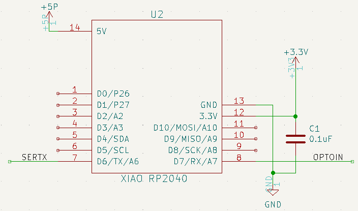
- XAIO RP2040 CPU
- Based on Adafruit QT Py RP2040 USB to Serial MIDI Friends design
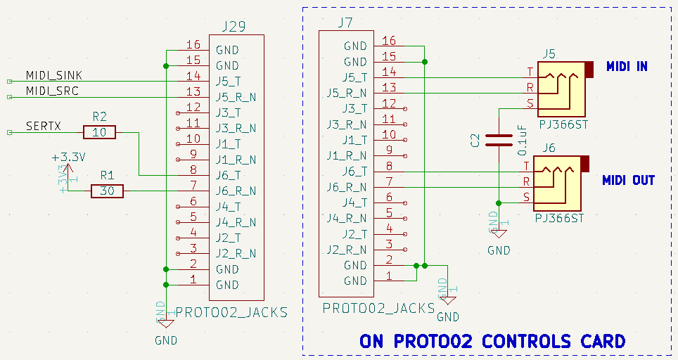
- MIDI on TRS A type connector
- J6 = MIDI Serial output
- J5 = MIDI Serial input (future feature)
Resources
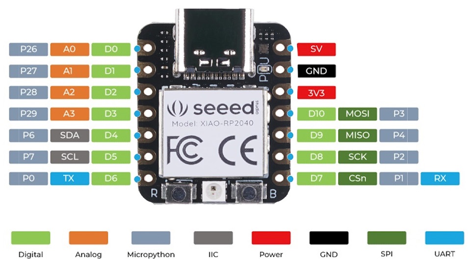
Seeeduino XIAO RP2040
There are 14 GPIO PINs on XIAO RP2040, on which there are 11 digital pins, 4 analog pins, 11 PWM Pins,1 I2C interface, 1 UART interface, 1 SPI interface, 1 SWD Bonding pad interface.
Design
XAIO RP2040 CPU
MIDI Jacks
- J5, J6 = PJ366ST
- Install both Pot/Jack headers/sockets
- Female sockets on Controls card
- Male Pins on Daughtercard
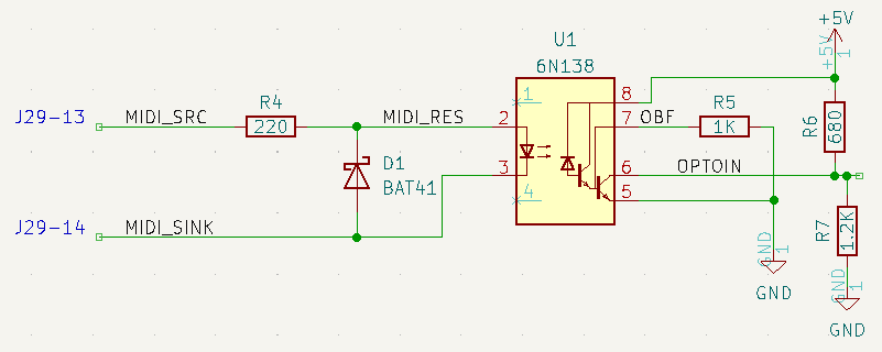
MIDI In
Daughtercard Prototyping Area
Software
- Adafruit MIDI Friends
- Bridges USB MIDI to Serial MIDI
- Takes in MIDI from the USB (typically from a PC running a MIDI player) and send out MIDI
- Maintains optical isolation on MIDI
- Bridges USB MIDI to Serial MIDI
- Listens to MIDI Channel 1
- Load CircuitPython to card (using v7.x)
- Press right button then insert USB cable
- Drive will appear on PC
- Drop CircuitPython uf2 onto the drive
- Drop application and libraries onto card - Drop as code.py to auto-run
- Download/run MIDIEditor
- Edit
- Settings
- MIDI Output
- Select CircuitPython Audio
- Load MIDI file (Free MIDI files sites)
- Click play button
