Difference between revisions of "ER-VCF-01 Rev 3 Assembly Sheet"
Jump to navigation
Jump to search
Blwikiadmin (talk | contribs) |
Blwikiadmin (talk | contribs) |
||
| Line 23: | Line 23: | ||
* [http://land-boards.com/ER-VCF-01/ibom.html Interactive BOM] | * [http://land-boards.com/ER-VCF-01/ibom.html Interactive BOM] | ||
** J2, J3 get mounted to the rear of the card | ** J2, J3 get mounted to the rear of the card | ||
| − | + | * D4-D9 - could be matched | |
| − | |||
| − | * D4-D9 - matched | ||
{| class="wikitable" | {| class="wikitable" | ||
Revision as of 22:51, 24 January 2023
Three card set
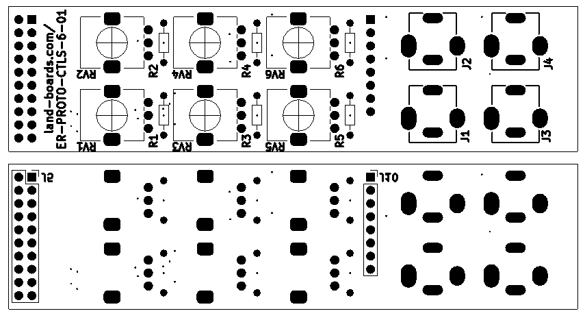
- PROTO-02 Front Panel
- PROTO-02 Controls Card
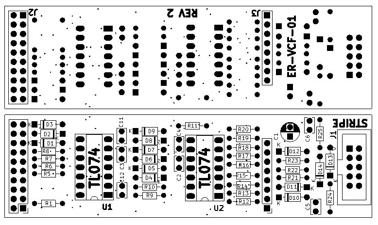
- ER-VCF-01 Analog Card
PROTO-02 Controls Card
- RV1, RV3 = DNP
- RV2, RV4, RV5, RV6 = B100K
- J1-J4 = PJ301BM
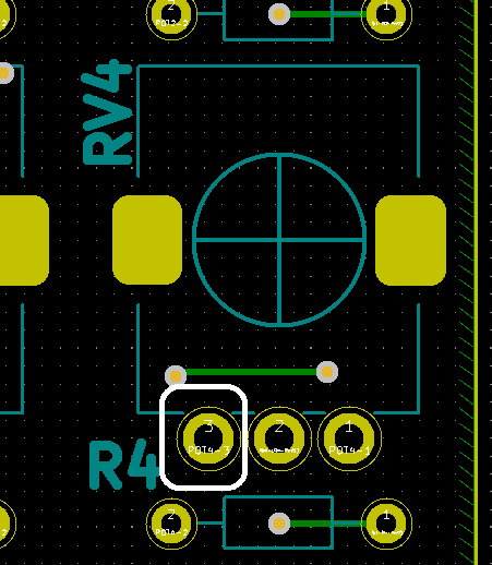
- R4, R6 = 100K
- R2, R5 = 0
ER-VCF-01 Analog Card
- Interactive BOM
- J2, J3 get mounted to the rear of the card
- D4-D9 - could be matched
| Find | Qty | Ref Des | Part Number | Find | Qty | Ref Des | Part Number | |
|---|---|---|---|---|---|---|---|---|
| 1 | 12 | D1-D12 | 1N4148 | 10 | 1 | C1 | 1uF | |
| 2 | 2 | D13, D14 | 1N5817 | 11 | 5 | C2-C4, C11, C12 | 1nF | |
| 3 | 2 | R1, R9 | 10K | 12 | 2 | C5, C6 | 0.1uF | |
| 4 | 6 | R2, R4, R7, R20-R22 | 100K | 13 | U1, U2 | TL074 | ||
| 5 | 1 | R5 | 47K | 14 | J1 | ER-PWR-2X5 | ||
| 6 | 4 | R2, R6, R8, R11 | 1K | 15 | J2 | HEADER, 2X8 (REAR) | ||
| 7 | 3 | R10, R12, R19 | 2.2K | 16 | J3 | HEADER, 1X8 (REAR) | ||
| 8 | 7 | R13, R14-R18, R23 | 33K | |||||
| 9 | 2 | R24, R25 | 10 |


