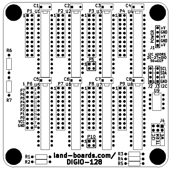
Difference between revisions of "DIGIO-128 Rev X4 Assembly Sheet"
Jump to navigation
Jump to search
Blwikiadmin (talk | contribs) |
Blwikiadmin (talk | contribs) |
||
| Line 73: | Line 73: | ||
== R6/R7 Option == | == R6/R7 Option == | ||
| − | * R6 | + | * R6 and R7 can be used to shift the address of the 64 bit version of the card from 0x20-0x23 up to 0x24-0x27 |
| + | * R6 pulls up A2 to Vcc (only if R7 is not installed) (64-bits only) | ||
| + | * R7 provide pull-up or pull-down for I2C address A2 line | ||
| − | === 128-bit option === | + | === DIGIO-128 - 128-bit option === |
* Leave R6 open (no resistor) | * Leave R6 open (no resistor) | ||
* Install jumper wire into R7 | * Install jumper wire into R7 | ||
| − | === 64-bit option === | + | === DIGIO-64 - 64-bit option === |
| − | * Typical - for I2C address = 0x20-0x23 leave | + | * Typical - for I2C address = 0x20-0x23 leave R6 open, install jumper wire into R7 |
* For I2C address = 0x24-0x27 leave R7 open, install 10K resistor in R6 | * For I2C address = 0x24-0x27 leave R7 open, install 10K resistor in R6 | ||
| + | * I2C chips get installed into top 4 locations | ||
Revision as of 13:01, 12 February 2021
Parts List
| Qty | Value | RefDes | Qty | Value | RefDes | |
|---|---|---|---|---|---|---|
| 8 | 0.1uF Cap | C1,C2,C3,C4,C5,C6,C7,C8 | 1 | CONN, 2X03 | J4 | |
| 1 (option) | 0 | R7 (option - below) | 2 | CONN, 1x4 | J2,J3 | |
| 2 (3) | 10K (1/4W) | R1,R2
R6 (option - below) |
1 | CONN, 1x5 | J1 | |
| 1 | 1K (1/4W) | R5 | 8 | CONN, 2x10 | P1,P2,P3,P4,P6,P7,P8,P9 | |
| 2 | 2.2K (1/4W) | R3,R4 | 2 | CONN, 2X2 | P10,P5 | |
| 1 | 24LC024-I/P | U9 | ||||
| 8 | MCP23017P | U1,U2,U3,U4,U5,U6,U7,U8 |
R6/R7 Option
- R6 and R7 can be used to shift the address of the 64 bit version of the card from 0x20-0x23 up to 0x24-0x27
- R6 pulls up A2 to Vcc (only if R7 is not installed) (64-bits only)
- R7 provide pull-up or pull-down for I2C address A2 line
DIGIO-128 - 128-bit option
- Leave R6 open (no resistor)
- Install jumper wire into R7
DIGIO-64 - 64-bit option
- Typical - for I2C address = 0x20-0x23 leave R6 open, install jumper wire into R7
- For I2C address = 0x24-0x27 leave R7 open, install 10K resistor in R6
- I2C chips get installed into top 4 locations
