Difference between revisions of "PE4302 RF Attenuator"
Jump to navigation
Jump to search
Blwikiadmin (talk | contribs) |
Blwikiadmin (talk | contribs) |
||
| Line 33: | Line 33: | ||
== My Build == | == My Build == | ||
| − | |||
| − | |||
| − | |||
| − | |||
| − | |||
[[file:PE4302_P1833-720px.jpg]] | [[file:PE4302_P1833-720px.jpg]] | ||
| Line 45: | Line 40: | ||
[[file:PE4302_P1832-720px.jpg]] | [[file:PE4302_P1832-720px.jpg]] | ||
| + | * A lot of designs use Arduino/OLED, etc to control the card - unnecessary | ||
| + | ** Could add noise from OLED | ||
| + | ** Doesn't need to switch too often | ||
| + | * Mount in [https://www.ebay.com/sch/i.html?_from=R40&_trksid=p2334524.m570.l1313&_nkw=80+50+20+project+enclosure+plastic&_sacat=0&LH_TitleDesc=0&_odkw=80mmx50mmx20mm+project+enclosure+plastic&_osacat=0 small 80mm x 50mm x 20mm project box] | ||
* SMA connectors | * SMA connectors | ||
** Board connector for one SMA | ** Board connector for one SMA | ||
Revision as of 22:42, 12 September 2021
Features
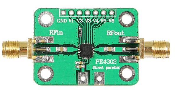
- PE4302 RF attenuator module
- Parallel immediate mode
- Program control gain attenuation range is from 0 to 31.5dB
- Bandwidth 1MHz to 4GHz
Specifications
- Power Supply Voltage
- 2.7-3.3 VDC - 3V typical
- Typical current 5mA
- Program control gain attenuation range
- 0~31.5DB
- 10K pull down resistors to ground
- Step size: 0.5DB
- Input/Output Impedance
- 50 ohm
- Bandwidth
- 1MHz~4GHz
- Attenuation value will differ under different frequency
- Max Input power (50Ω)
- +30 dBm
- 1W = 7.1V RMS
- Connectors
- SMA-female
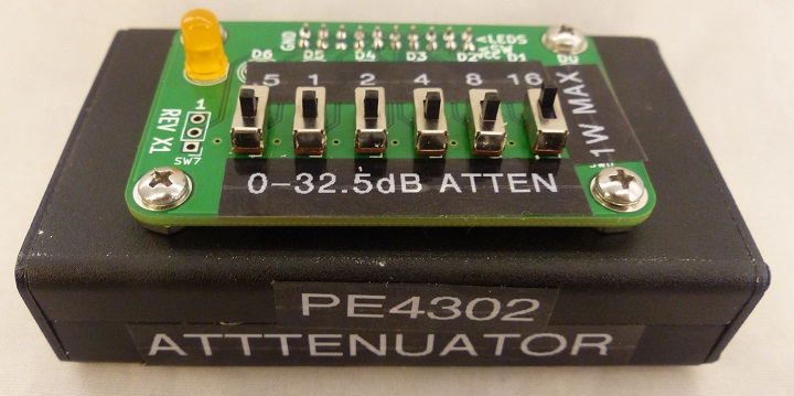
My Build
- A lot of designs use Arduino/OLED, etc to control the card - unnecessary
- Could add noise from OLED
- Doesn't need to switch too often
- Mount in small 80mm x 50mm x 20mm project box
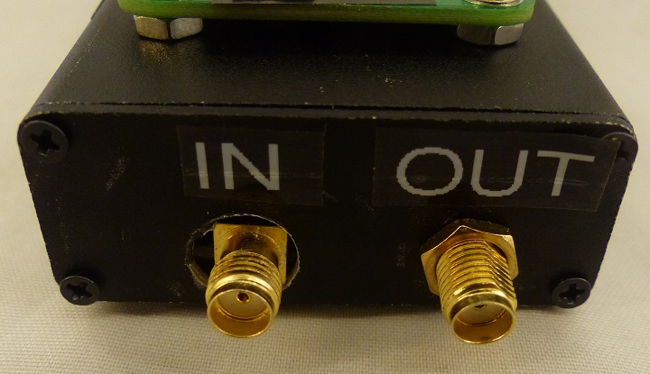
- SMA connectors
- Board connector for one SMA
- Short cable male SMA to SMA female bulkhead SMA for other end
- PE6402 remove straight header, replace with right angle connector over card
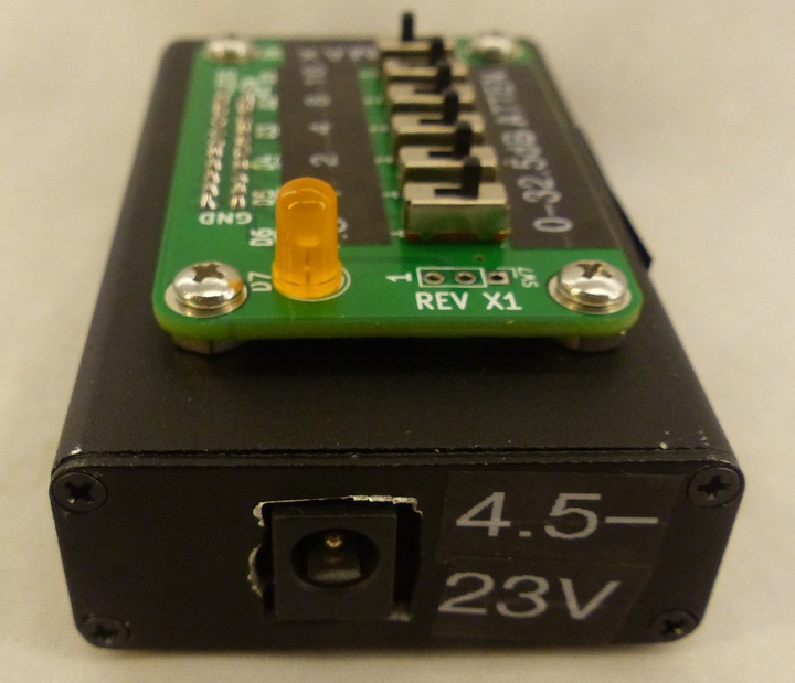
- Mini360 Adapter Board for wide input voltage range
- 4.75-23V input
- 3V output
- Concern over EMI?
- Right angle connector 2x3 min
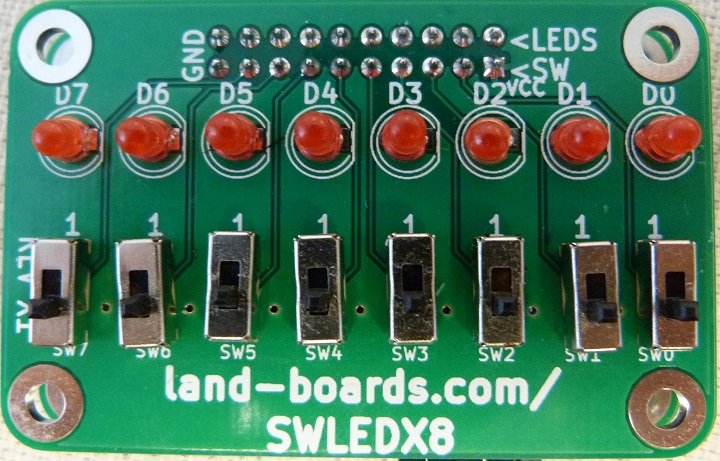
- Use SWLEDX8 to control attenuation selection
- Right angle 2x10 under card for low profile installation
- Use SW1-SW6 switches (centered horizontally on card)
- Digital Input High 0.7xVDD in V = 2.1V
- Using 1.2K-1.5K pullup to counter the 10K pulldowns on the card = 2.6V
- When switch is on/low - 3V / 1.5K = 2 mA
- Adds to current 2 mA x 6 = 12 mA when all switches are low
- Use D7 for power indication
- Vf = 1.8V, 3V-1.8V = 1.2V, 3 mA for lower light level - use 470 ohm resistor
- Cabling
- 1x7 pin PE4302 connector (Use 1x8, ignore 8th pin)
- 2x10 Dupont connector for SWLEDX8
- Ground, power to D7 LED, 6 switches
- 2x3 Dupont connector with pins from Mini360 Adapter Board
Measurements
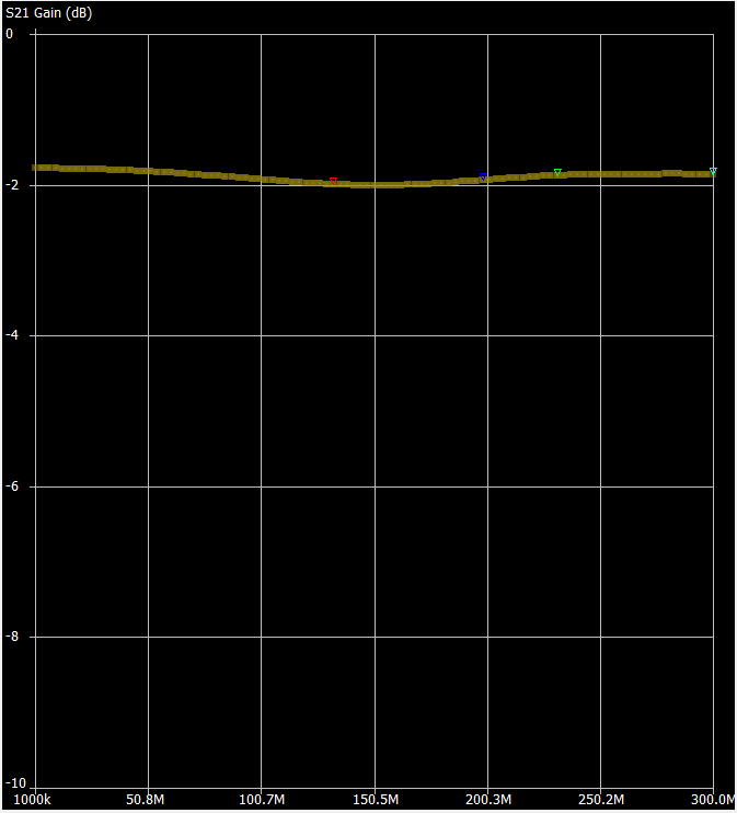
- NanoVNA
- Sweeping from 1-300 MHz
- All switches set to GND
- Approx 2 dB insertion loss
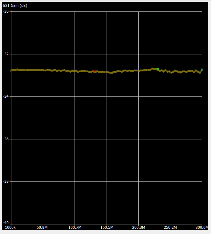
- S21 Gain zoomed in
- All switches set to GND
- Min -1.2 dB insertion loss
References
- DuWayne's Arduino based attenuator
- Hackaday project page
- Peregrine Semiconductor's page - Chip maker
- PE4302 tswfi - Simple attenuator built with PE4302 and Arduino "pro micro".
