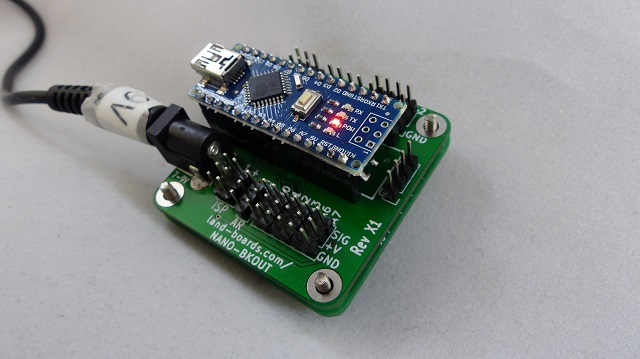
NANO-BKOUT
Contents
Arduino Nano Breakout card
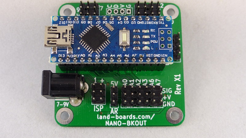
This card breaks out a Arduino Nano (not supplied with NANO-BKOUT card) into GVS (Ground-Voltage-Signal) headers for easy connection to external sensors.
Features
- Breakout card for the Arduino Nano
- NANO (not supplied) is:
- Inexpensive ($6-$7 US, $2.50 China), multiple sourced part
- 5V, 16 MHz
- Installs onto female header/removable
- DC regulator
- Microprocessor ATMega328 Comparable with Arduino UNO
- Mini USB connector
- Reset switch
- NANO-BKOUT has
- DC Power Jack
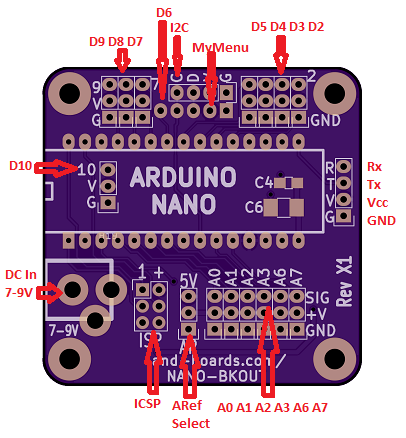
- GVS connections for most digital/analog signals
- Ground and power connections for each digital lines simplify power distribution to external functions such as sensors
- Additional analog input signals (over the Arduino UNO)
- ICSP (In-Circuit System Programmer) header
- I2C header
- Aref voltage selection header
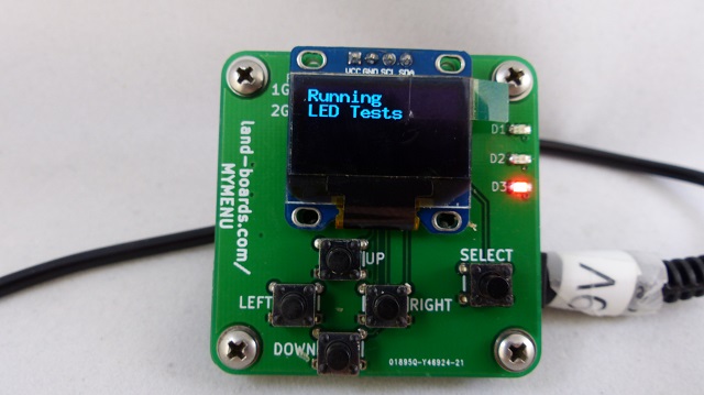
- Direct connection to MyMenu card
- I2C Interface
- D6 connection for interrupt line
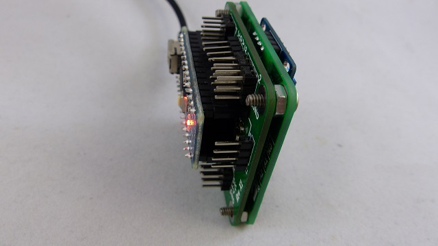
- Located in mirrored location on both boards to allow the MyMenu to mount to the rear
- 49x49mm form factor
- (4) 4-40 mounting holes for installation into enclosures
- Rounded corners to allow card to be installed into enclosure corners
Connectors - Rev X1
ISP Connector
- D12
- +5V
- D13
- D11
- RST*
- GND
(H18) AREF Select Jumper
- 1-2 = External AREF (via shared power pins)
- 2-3 = Use 5V as AREF = Factory position
NANO-BKOUT Plus MyMenu
- NANO-BKOUT
- MyMenu
Testing
Board Test
Hardware
- UUT
- AREF Jumper installed from pin 2 to 5V Legend
- Arduino NANO
- POWER-49MM card
- 2x LED-TEST-2 cards
- Cable Set
- USB or external DC power
Cabling
- The cable wires the LEDs to the UUT pins.
- Pins A6 and A7 are untested since they are analog inputs only.
Test Station Cable Marking and installation locations are:
- L01 - Goes to LED-TEST-2 card #1 LEDS 1-4
- L05 - Goes to LED-TEST-2 card #1 LEDS 5-8
- L09 - Goes to LED-TEST-2 card #1 LEDS 9-12
- L13 - Goes to LED-TEST-2 card #1 LEDS 13-16
- L17 - Goes to LED-TEST-2 card #2 LEDS 1-4
- G1 - Goes to POWER-49MM card on "-" pins
- G5 - Goes to POWER-49MM card on "-" pins
UUT Cable Marking and installation locations are:
- D3 - Goes to UUT D3 (and D2) location
- D5 - Goes to UUT D5 (and D4) location
- D5 - Goes to UUT D5 (and D4) location
- I2C - Goes to UUT I2C location
- D8 - Goes to UUT D8 (and D7) location
- D9 - Goes to UUT D9 location
- D10 - Goes to UUT D10 location
- SER - Goes to Serial location
- ISP - Goes to UUT ISP location
- A0 - Goes to UUT A0 (and A1) location
- A2 - Goes to UUT A2 (and A3) location
Test Software
Board Revs
Rev X2
- Same netlist as X1
- Moved I2C connector under the Nano to avoid interference with [MyMenu] connection
Rev X1
- Tough to solder in the I2C connector when used with MyMenu card
Links
Arduino Nano Page Arduino Nano schematic

