Features
Operation
- Receives single Gate on J1
- RV1 controls OUT 1
- RV2 controls OUT 2
- RV3 is mode for OUT 1
- RV4 is mode for OUT 2
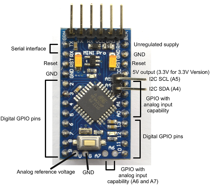
Arduino Pro Mini
- Works with ATMega168 (or 328)
- Program from FTDI

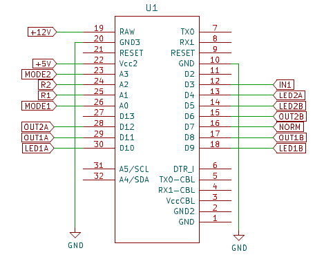
Arduino Pins

Controls
- RV1 - Probabilistic ratio for Output 1
- Center = 50-50, CCW = Out1A on 100%, CW = 0% on OUT1B
- Inserting J3 jack disables RV1
- RV2 - Probabilistic ratio for Output 2
- Center = 50-50, CCW = Out1A on 100%, CW = 0% on OUT1B
- Inserting J3 jack disables RV1
- RV3 - OUT 1 Mode
- 7-12 o'clock = Normal Mode drives only OUT1A or OUT1B
- 12-5 o'clock = Drives both OUT1A and OUT1B
- RV4 - OUT 2 Mode
- 7-12 o'clock = Normal Mode drives only OU21A or OUT2B
- 12-5 o'clock = Drives both OUT2A and OUT2B
Jacks
J1 - Gate
- 0.6V threshold GATE input
J2 - Random %
- 0-5V control input
- Inserting jack disables RV1
- 0V = 100% on OUT1A, 2.5V = 50% on OUT1A/OUT1B, 5V = 100% on OUT1B
J3 - Out1A
- Gate output 1
- 0-5V digital output
J4 - Out1B
- Gate output 1
- 0-5V digital output
J5 - Out2A
- Gate output 2
- 0-5V digital output
J6 - Out2B
- Gate output 2
- 0-5V digital output
Schematic
Software
- Arduino IDE
- Pot/GATEs Test
- Used for testing the hardware works
- Reads (4) pots and prints values to monitor, write values to serial
- Toggles GATE outs - one at a time
- Tests RV1/J2 loopback
- Simplest Version 1
- 2 pots, one for OUT1A/B, other for OUT2A/2B
- Still pretty simple - Version 2
- Adds (2) mode control knobs
- 7 o-clock = 12 o'clock = Normal mode
- 12 o-clock - 5 o=clock = Send Outputs on both OUTxA and OUTxB
Sketch uses 1990 bytes (13%) of program storage space. Maximum is 14336 bytes.
Global variables use 13 bytes (1%) of dynamic memory, leaving 1011 bytes for local variables. Maximum is 1024 bytes.
Build


- Covered RV5, RV6 holes with black duct tape
- Labels are White on Black P-Touch labels
Parts List

| Find
|
Qty
|
Ref Des
|
Part Number
|
| 1
|
1
|
R35
|
1K
|
| 2
|
1
|
C1
|
10uF
|
| 3
|
5
|
D1-D5
|
BAT41
|
| 4
|
1
|
J9
|
Conn, IDC, Box, 2x5
|
| 5
|
2
|
LED1, LED2
|
LED_Dual_2pin
|
| 6
|
1
|
Q1
|
2N3904
|
| 7
|
1
|
R1
|
10
|
| 8
|
1
|
U1
|
ARDUINO PRO MINI
|
|
|
|
|
|
| 11
|
6
|
RX2, RX7, RX9, RX15, RX17
|
1K
|
| 12
|
2
|
RVX1, RVX2
|
100K
|
| 13
|
2
|
RX3, RX4
|
220
|
| 14
|
2
|
RX11, RX13
|
100K
|
| 7
|
6
|
JX1-JX6
|
Jack
|


