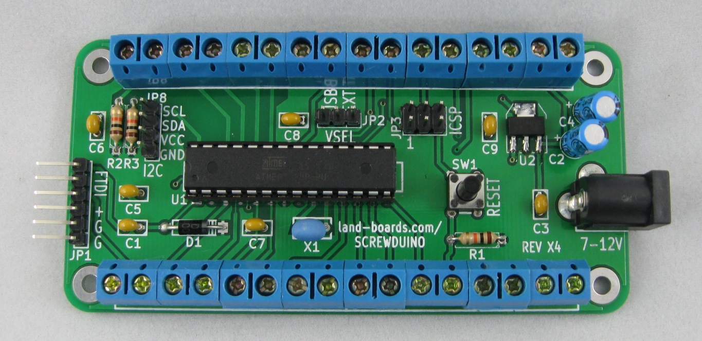
Screwduino
Contents
Features
- Arduino UNO Compatible (Arduino bootloader)
- ICSP header for program download
- Standard 6-pin FTDI connector
- 4-pin I2C connector
- Reset switch
- Other than power regulator only uses through-hole parts
- 5mm pitch screw terminal blocks
- Four (4) 4-40 mounting holes with clearance for screw heads, standoffs and/or nuts
- 7-12V DC on standard 2.1mm DC power connector
- Power selection jumper (FTDI, Regulator, Screw Terminals)
Design Advantages
Gets away from all of the painful wire jumpers and pins that constantly come loose. Makes the step from prototype to final design much easier.
| Method | Material Costs | Labor Tasks | Power/Ground pins | Wires secure? | Mounting | I2C Support |
|---|---|---|---|---|---|---|
| Processor | UNO - $30 | Strip wires and solder to parts | 3 GND1 PWR | Wires don't stay in holes with any stress. | Poor | No connector |
| Breadboards | Uno - $30 +Breadboard $10 | Strip wires or use breadboard wires | 120 each PWR/GND for 700 point breadboard | Moderately secure since the holes are usually “tight” | Poor | No connector |
| ProtoShields | Uno - $30 +Shields - $15 | Lot of time- consuming soldering of custom wiring | Vary but usually enough although maybe not connectorized in the best use | Wires typically soldered so secure | Poor | No connector |
| Sensor Shields | Uno - $30 +Shields - $15 | Use custom wires | Excellent at 1 per Arduino Digital/Analog pin | Connectors are secure | Poor | Yes |
| Screw Wings | Uno - $30 + Wing Shield - $15 | Strip wires and solder to parts | Varies depending upon shield | Connections very secure | Poor | No connector |
| Screwduino | $30 (est) | Strip wires and solder to parts | 5 – Ground 4 – PowerAdditional on other connectors | Connections very secure | Excellent | Yes |
Screwduino Schematic
[ Screwduino Schematic]
Screwduino Layout
Power
Measured 15 mA with 9V external power input (no loads but running program).
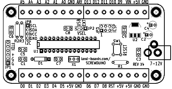
Card Power Source - VSEL Jumper
- This jumper selects the power source for the card
- Install jumper across the USB pins to power the card from the FTDI interface.
- Install jumper across the EXT pins to power the card from the DC jack.
- Leave the jumper off when powering the card from the ISP connector.


