
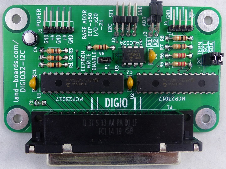
Features
- 32-bit Digital I/O
- 24LC024 ODAS Personality EEPROM
- pid = 6
- Write Enable jumper protects EEPROM against accidental damage
- I/O Connector is inexpensive/standard DB-37 Female
- I2C Interface
- Daisy-chain I2C connector
- I2C Termination jumpers for end of I2C chain
- I2C Address select jumper (2 addresses - can support up to 4 cards)
- Power Options
- Supports 3.3V or 5V signal levels
- Fuse protected power output on DB-37
- Power connector (not required for minimal loads
- ODAS form factor (width is 95 mm)
- 6-32 Mounting holes
Connectors
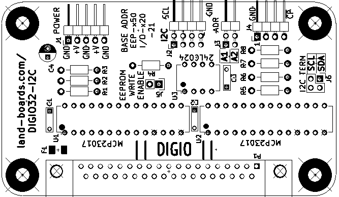
J1 - Power
- Optional use since card can be powered from I2C Daisy-chain connector pins
- Pinout
- GND
- Vcc
- GND
- Vcc
- GND
J2 - Daisy-Chained I2C
- 2x4 header
- Duplicated signals on each pair
- SCL
- SDA
- Vcc
- GND
J3 - Address Offset Jumpers
- Set the address offset for the MCP23017 and EEPROM
- MCP23017 base addresses are 0x20-0x21
- Card can be set to
- 0x20-0x21
- 0x22-0x23
- 0x24-0x25
- 0x26-0x27
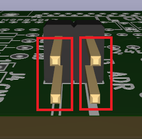
- Jumpers orientation
J4 - Interrupt Out, Card Present
- GND
- INT1*
- INT0*
J5 - EEPROM Write Enable
- Install to allow writes to EEPROM
- Remove to disallow writes to EEPROM
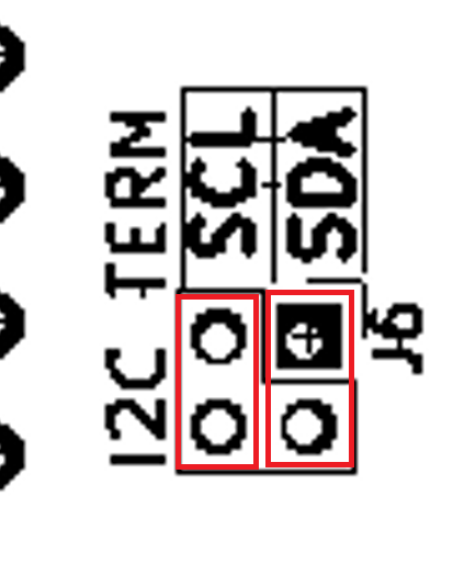
J6 - I2C Terminators
- Install to terminate I2C lines
- Terminators should only be installed at one point in the chain at the end of the chain
- Orientation of jumpers
P1 - DB-37 Female Pinout
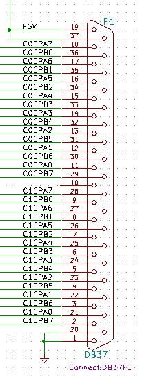
P1 - DB-37 Female Pin List
- Useful list for mapping pins to applications
- Can copy-paste this table to spreadsheet
| DB37Pin
|
Descr
|
|
DB37Pin
|
Descr
|
| 1
|
GND
|
|
20
|
GND
|
| 2
|
C1PB7
|
|
21
|
C1PA0
|
| 3
|
C1PB6
|
|
22
|
C1PA1
|
| 4
|
C1PB5
|
|
23
|
C1PA2
|
| 5
|
C1PB4
|
|
24
|
C1PA3
|
| 6
|
C1PB3
|
|
25
|
C1PA4
|
| 7
|
C1PB2
|
|
26
|
C1PA5
|
| 8
|
C1PB1
|
|
27
|
C1PA6
|
| 9
|
C1PB0
|
|
28
|
C1PA7
|
| 10
|
N/C
|
|
29
|
C0PB7
|
| 11
|
C0PA0
|
|
30
|
C0PB6
|
| 12
|
C0PA1
|
|
31
|
C0PB5
|
| 13
|
C0PA2
|
|
32
|
C0PB4
|
| 14
|
C0PA3
|
|
33
|
C0PB3
|
| 15
|
C0PA4
|
|
34
|
C0PB2
|
| 16
|
C0PA5
|
|
35
|
C0PB1
|
| 17
|
C0PA6
|
|
36
|
C0PB0
|
| 18
|
C0PA7
|
|
37
|
F+5V
|
| 19
|
F+5V
|
|
|
|
P1 - DB-37 to DB37RIBBON Pin list
- The card canbe used with a DB37RIBBON RB-38 to ribbon adapter card
- This is the map of the pinout when used with the DB37RIBBON card
- The DB37RIBBON adapter has a male connector when used with this card
| DB37 Pin
|
Descr
|
Conn_40
|
|
DB37 Pin
|
Descr
|
Conn_40
|
| 1
|
GND
|
1
|
|
20
|
GND
|
2
|
| 2
|
C1PB7
|
3
|
|
21
|
C1PA0
|
4
|
| 3
|
C1PB6
|
5
|
|
22
|
C1PA1
|
6
|
| 4
|
C1PB5
|
7
|
|
23
|
C1PA2
|
8
|
| 5
|
C1PB4
|
9
|
|
24
|
C1PA3
|
10
|
| 6
|
C1PB3
|
11
|
|
25
|
C1PA4
|
12
|
| 7
|
C1PB2
|
13
|
|
26
|
C1PA5
|
14
|
| 8
|
C1PB1
|
15
|
|
27
|
C1PA6
|
16
|
| 9
|
C1PB0
|
17
|
|
28
|
C1PA7
|
18
|
| 10
|
N/C
|
19
|
|
29
|
C0PB7
|
20
|
| 11
|
C0PA0
|
21
|
|
30
|
C0PB6
|
22
|
| 12
|
C0PA1
|
23
|
|
31
|
C0PB5
|
24
|
| 13
|
C0PA2
|
25
|
|
32
|
C0PB4
|
26
|
| 14
|
C0PA3
|
27
|
|
33
|
C0PB3
|
28
|
| 15
|
C0PA4
|
29
|
|
34
|
C0PB2
|
30
|
| 16
|
C0PA5
|
31
|
|
35
|
C0PB1
|
32
|
| 17
|
C0PA6
|
33
|
|
36
|
C0PB0
|
34
|
| 18
|
C0PA7
|
35
|
|
37
|
F+5V
|
36
|
| 19
|
F+5V
|
37
|
|
N/C
|
N/C
|
38
|
| N/C
|
N/C
|
39
|
|
N/C
|
N/C
|
40
|
Schematic
Testing
- There are two card tests
- Bounce LED test
- Good for visual verification/debugging
- Only tests outputs from UUT
- Card to card test
- More flexible/faster test
- Tests both inputs/outputs from/to the card
Cards
Card Test Procedure
- Power up Test Station/UUT
Program EEPROM
- Some UUTs have Personality EEPROMs
- Run
chdir "/lbcards/ODAS_EEPROM"
load "ODASEEPROM.bas"
run
- If the UUT EEPROM is already programmed, the result is:
Found device at 0x50
Personality EEPROM contents
 Signature = ODAS
 Version = 1
 Rsvd = 0
 NumAtoms = 2
 eeplen = 96
 uuid = 0000000000000000
 Product ID = 6 (DIGIO32-I2C)
 vslen = 32
 pslen = 32
 Vendor String = LAND-BOARDS.COM
 Product String = DIGIO32-I2C
Re-write (Y/N)?
Bounce LED Test
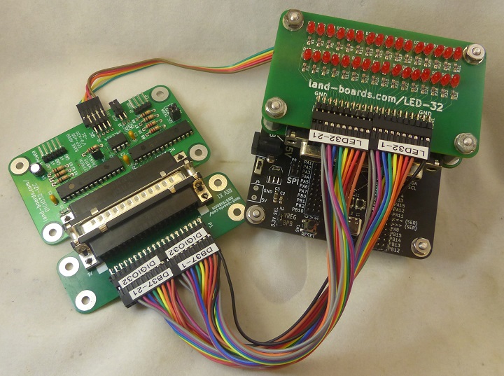
chdir "/lbcards/GPIO32"
load "DIGIO32I2C-01.bas"
run
- Should see the LEDs go around the LED-32 card
- Hit any key to stop (after finishing rotation)
Card-to-Card Test
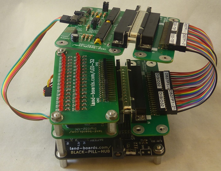
load "DIGIO32I2C-02.bas"
run
- Program will halt if failure
- Prints out a pass count
- Hit any key to stop
Drivers
Assembly Sheet


