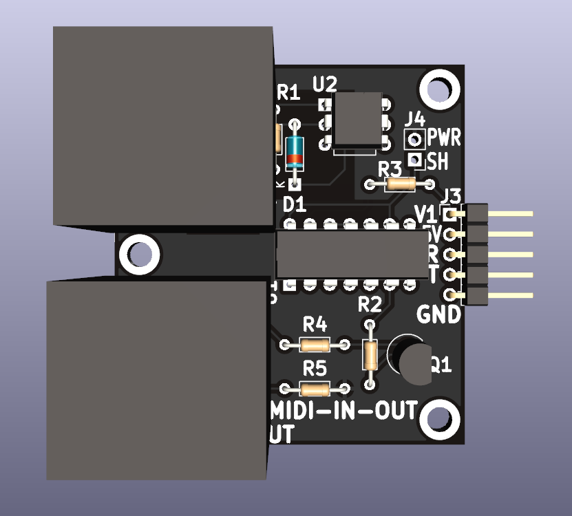
MIDI-IN-OUT
Contents
Features
- Module for Prototyping Synthesizer components
- MIDI In/Out Jacks
- Opto-isolated MIDI Input
- 5V MIDI interface
- 3.3V or 5V Serial connections
- MIDI In is opto-isolated
- (2) 4-40 Mounting holes
Connectors
J1 - MIDI In
- Opto-isolated input
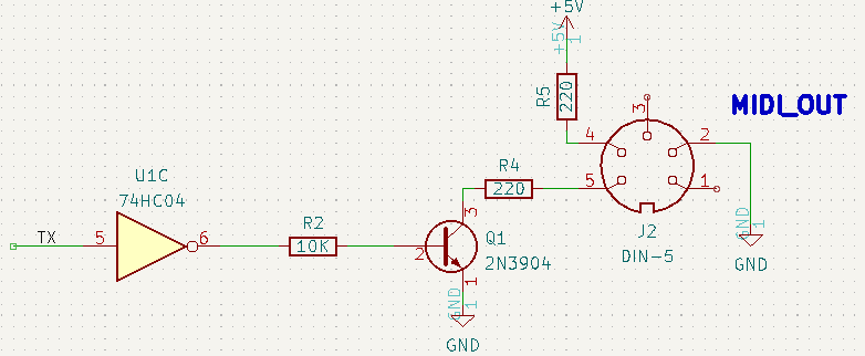
J2 - MIDI Out
J3 - Serial/Power
- Pinout
- V1 (3.3V or 5V
- 5V
- Receive data (out of card)
- Transmit (in to card)
- GND
J4 - Short V1 to 5V
- Short J3-1 to J3-2
- Used when Host Serial interface is 5V
- Open when Host Serial interface is 3.3V
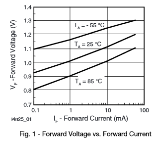
- LED Current vs voltage
- Output transistor capacitance
- Switching Time
Drive Circuit
- 4N25 Optocoupler
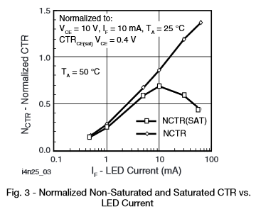
- DC Current Transfer Ratio
- Vf(LED) = 1.2V
- R(total) = 220 * 3 = 660 Ohms
- V(drive) = 5V
- I(LED) = 5.7 mA
- CTR = 50%


