Sw5Way
Contents
Five Way Switch
Up, down, left, right and select all in one single button.
As someone who has messed around with buttons for menu navigation including using five separate switches, wires, resisstors, etc, I think that this is a great, little design. It's s a small form factor five way switch. If anything, it's too small.
Thanks to LadyAda/Adafruit for https://www.adafruit.com/products/504 carrying the part. Also http://www.mouser.com/Search/ProductDetail.aspx?R=SKQUCAA010virtualkey68800000virtualkey688-SKQUCA available on Mouser for a few cents less.
This design borrows heavily from the work of others (resistor network into a single analog pin, use of the switch, etc) and adds the innovation of making it all usable in real world applications by providing four solid mounting holes on the corners of the switch make it easy to mount to any panel.
Prototype Received/Built (2012-07-05)
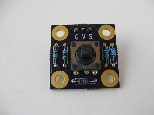
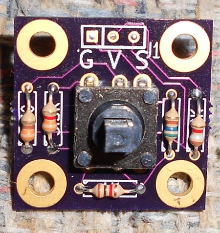
Here's version 1 of the board. Functions great electrically. Works nice on a breadboard although it pivots on the pins into the breadboard when you push on the directional buttons. http://oshpark.com LAEN's service took a while but the boards really look nice and are very solderable - first rate quality at a great price.
Issues with v1 Design - Lessons Learned
The GVS pins are too small to insert a BERGSTIK header.
Used the SIP-3 footprint which isn't intended for the larger 0.025" pads. I've made this mistake before.
Should have used the PIN_ARRAY library,
Built one board with wires soldered into the GVS holes.
Built two boards with pins mounted to the surface on the rear side. It's a bit fragile, but it works.
Used the R3 footprint in KiCad for the resistors.
Didn't realize these holes are spaced too closely together for 1/4W resistors.
1/8W resistors worked really well there and they are lower profile.
All of the parts (except the 1.8K are qty 10 or more in the 1K resistor) in the RadioShack 1/8W assortment.
Probably SMT resistors would work well here.
Silkscreen resistor marked 580 should be 560.
The 560 and 1.8K resisors are close to a mounting pad.
Silkscreen fir GVS header is on the wrong side of the board.
GVS Silkscreeen is too big and not well lined up.
A ground plane might be good for noise reduction although I don't think it's really necessary.
Noted - anticipated mounting complications.
Wasn't able to determine the distance that the the switch is from the shoulder of the switch to the top of the PCB from the spec but I measured 0.15" with my calipers.
4-40 nuts are .09" so a stack of 2 nuts is about 0.18"
The switch fits pretty low profile to the card.
Washer stackup might work just fine.
Description of the Design
Purpose is to have a menu navigation control in a small size. This design can operate as a small joystick replacement. Rather than having five separate buttons, this design is all done in one compact part with solid mounting.
SKQU_D_33.GIF
The switch (http://www.mouser.com/Search/ProductDetail.aspx?R=SKQUCAA010virtualkey68800000virtualkey688-SKQUCA Mouser) (http://www.alps.com/products/WebObjects/catalog.woa/E/HTML/Switch/Tact/SKQU/SKQUCAA010.html ALPS, SKQUCAA010) has five positions, left, right, up, down and press in. These are connected to a five resistor network which encodes a unique output voltage for each key press. Common resistor values were chosen to make this an easy to find parts solution.
SKQU_D_31.GIF
SKQU_D_32.GIF
SKQU_C_2.GIF
Output Voltage Values
This is the same resistor network used in the DFRobot (and others) http://www.ebay.com/sch/?_nkw=lcd%20keypad%20shield%20arduino&clk_rvr_id=361983412089 LCD Keypad shield.
 	Calc	Meas	 	total res	res to gnd	min	max	cMin	cMax
Right	0.0	0.0	1800	 	 	0	0.3873239437	0	79
up	0.8	0.8	330	2130	330	0.3873239437	1.2268073385	79	251
down	1.7	1.8	580	2710	910	1.2268073385	2.1265453894	251	435
left	2.6	2.7	1000	3710	1910	2.1265453894	3.145121909	435	643
select	3.7	3.8	3300	7010	5210	3.145121909	4.3580599144	643	892
none	5.0	5.0	 	 	 	4.3580599144	5	892	1023
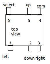
Switch Pinout
Connectors
Single GVS (Ground, Voltage, Signal) style connection.
Pin 1 = Ground
Pin 2 = Voltage (+5V)
Pin 3 = Signal - analog output
Parts List
Ref Des	Value	Mfg	Mfg PN	Vendor	Vendor PN
J1	CONN_3	FCI	68001-203HLF	Mouser	649-68001-203HLF
R1	3.3K	Xicon	271-3.3K-RC	Mouser	271-3.3K-RC
R2	1K	Xicon	271-1K-RC	Mouser	271-1K-RC
R3	560	Vishay	CCF07560RJKE36	Mouser	71-CCF07560RJKE36
R4	330	Vishay	CCF07330RJKE36	Mouser	71-CCF07330RJKE36
R5	1.8K	Vishay	CCF071K80JNE36	Mouser	71-CCF071K80JNE36
SW1	SW5Way	ALPS	SKQUCAA010	Mouser	688-SKQUCA
Mounting Holes
Four 4-40 mounting holes surround the switch for solid mechanical support of the switch. 5.18 mm - 1.00 mm (panel thickness) Standoff height - using 1/4" tall, 3/16" wide hex standoffs (http://www.digikey.com/scripts/DKSearch/dksus.dll?Detail&itemSeq=116545192&uq=634766755355038882 Keystone, pn 1891).


