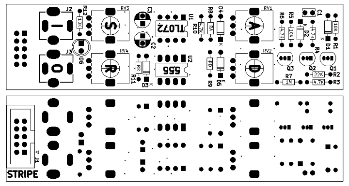
ER-ADSR-555-01 Rev 1 Assembly Sheet
Parts List
- Rework Instructions - Do cuts before installing parts
| Find | Qty | Ref Des | Part Number | Find | Qty | Ref Des | Part Number | |
|---|---|---|---|---|---|---|---|---|
| 1 | 4 | R1, R5, R11, R12 | 10K | 13 | 3 | RV1, RV2, RV4 | A1M | |
| 2 | 1 | R2 | 22K | 14 | 1 | RV3 | B10K | |
| 3 | 4 | R3, R4, R6, R9 | 4.7K | 15 | 1 | J1 | Conn_02x05 | |
| 4 | 1 | R7 | RA (100) | 16 | 2 | J2, J3 | PJ-301BM | |
| 5 | 1 | R8 | RD (100) | 17 | 1 | U1 | TL072 | |
| 6 | 1 | R10 | RR (100) | 18 | 1 | U2 | NE555N | |
| 7 | 5 | D1-D5 | 1N4148 | 19 | 1 | D6 | LED, 5MM | |
| 8 | 2 | U1, U2 | SOCKET, IC, 8 PIN | |||||
| 9 | 1 | C1 | 10nF, 2.54MM PITCH | |||||
| 10 | 1 | C2 | 10uF, 2.54MM PITCH | |||||
| 11 | 1 | C3 | 1uF, 2.54MM PITCH | |||||
| 12 | 3 | Q1, Q2, Q3 | 2N3904 |
Notes
- Two PCB set
- Front panel
- Controls/analog card
- Parts are in order of installation
- Lowest first
- Resistor footprints are for 1/8W resistors but can fit 1/4W resistors
- Use Front Panel to align pots/connectors
- LED standing up and through panel

