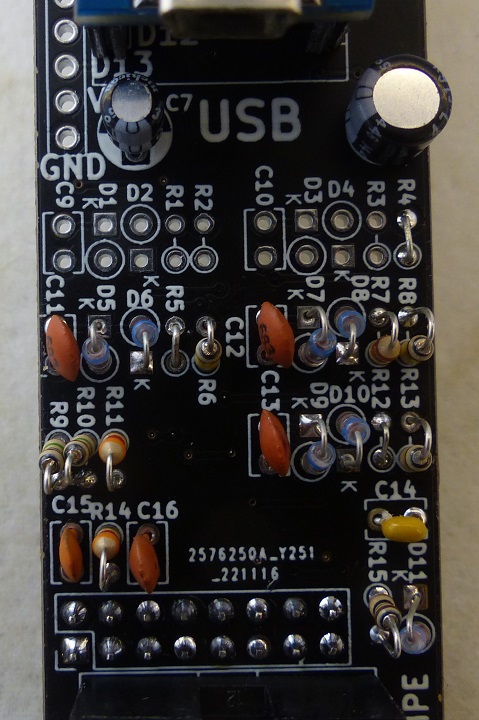
ER-MOZZI-DB-03
Revision as of 14:46, 25 January 2023 by Blwikiadmin (talk | contribs) (→Jacks Pin Protection Circuit)
Features
- Daughtercard to ER-PROTO-02 card
- Uses Front Panel and Controls card
- Controls card populated as required
- Up to 6 Pots
- Up to 5 in/out jacks
- High Def Sound output jack
- Controls card populated as required
- Uses Front Panel and Controls card
- Arduino NANO
Arduino Pins
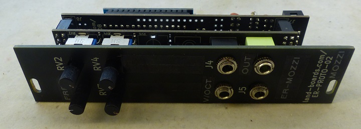
- The ER-PROTO-02 controls card has 6 pots (RV1-RV6) and 6 jacks (J1-J6)
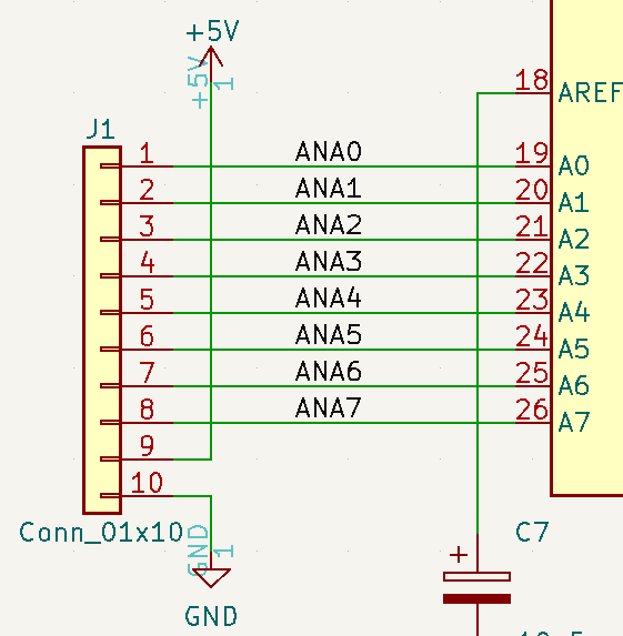
- The Arduino NANO has 8 Analog Inputs (0-7)
- The Arduino NANO has 11 Digital I/O pins (2-13)
- 6 Pots are brought into the card
- 6 Jacks are brought into the card
- J1-J5 Jacks can be used for analog inputs, digital inputs or digital outputs
- J6 Jack is a dedicated output (J6) connected to Hi Def output Arduino pins D9, D10
Jacks Pin Protection Circuit
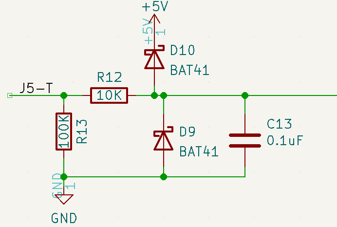
- Example circuit configured as input
- Same circuit on all 5 J1-J5 jacks
- Configured as input
- I/O Protection
- Diode Clamps
- Series resistor (R12 in example)
- Works along with diode clamps
- 10K Typical value
- Parallel resistor (R13 in example)
- 100K typical value
- Lightly pulls input to ground when no jack is connected
- Parallel capacitor (C13 in example)
- 10nF or 0.1uF are typical values
- Smooths analog input (noise reduction)
- 0 Ohm Series resistor on Controls card for 5V inputs
- Goes to jack tip pin
- I/O Protection
- Configured as output
- I/O Protection - Diode Clamps
- 0 Ohm Series resistor (R12 in example)
- DNP (Do Not Populate) Parallel resistor (R13 in example)
- DNP Parallel capacitor (C13 in example)
- Typical 470 or 1K Ohm Series resistor on Controls card
- Goes to jack tip pin
- Works along with diode clamps
Jacks/Headers
J1 - Arduino Analog Pins
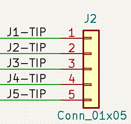
J2 - Jacks Pins
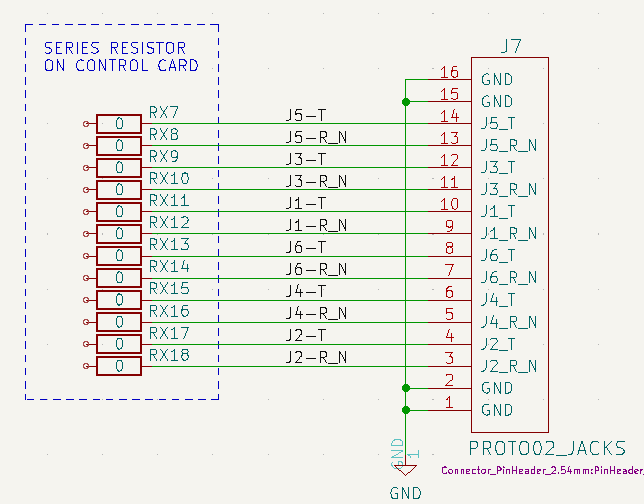
J7 - Jacks connections to Controls card
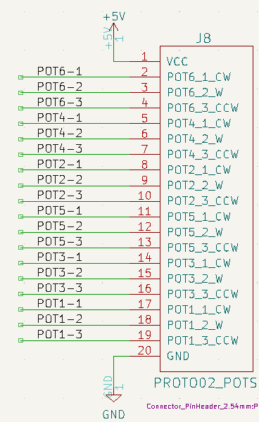
J8 - Pots connections to Controls card
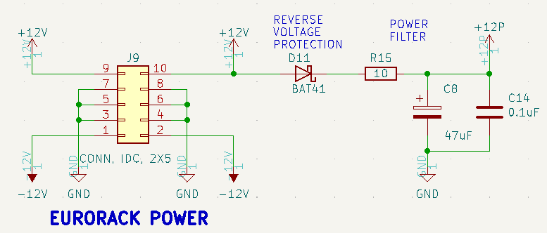
J9 - Eurorack Power
- Power filter
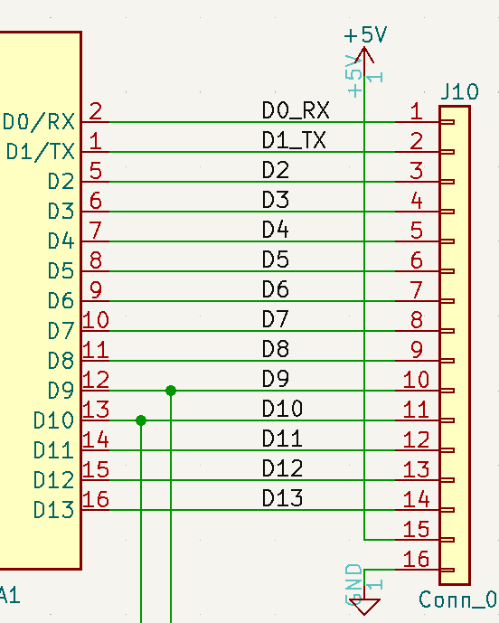
J10 - Arduino Digital Pins
Software / Example Projects
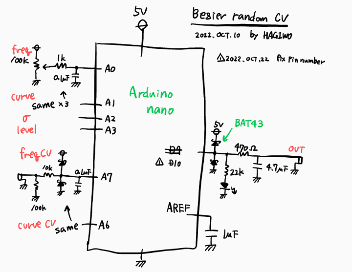
- HAGIWO Bezier curve random CV generator
- HAGIWO Envelope Generator Module
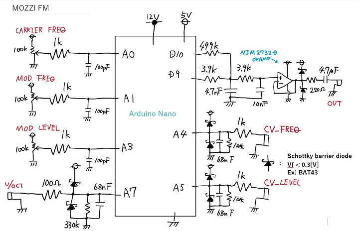
- HAGIWO FM VCO Module
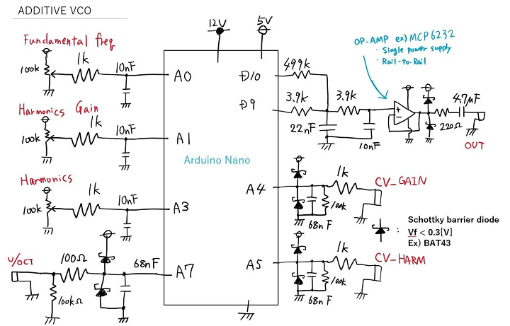
- HAGIWO Additive VCO (harmonic addition VCO)
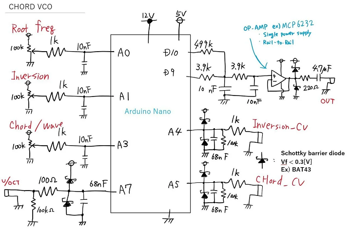
- HAGIWO CHORD VCO with mozzi library
- Using Mozzi Library With 5 Potentiometers
- Atari Punk Synth V2
- Arduino Multi-pot Mozzi FM Synthesis
- Arduino mozzi FM VCO Module for 650 yen - Modular synth self-made
- Nuts and Volts AUDUINO Synth build for the Arduino NANO
- MozMo = ATMega328 plus FTDI
HAGIWO MOZZI builds
- HAGIWO builds
- Pots
- Install RV1-RV4 = 100K
- Install series resistor R1-R3 1K
- Install Pull-up/Pull-down jumpers
- Jacks
- J3-J5 = PJ398SM
- J6 = PJ366ST
Additive VCO
- 3 pots (Fundamental Frequency, Harmonics Gain, Harmonic)
- 3 CV input jacks (V/Oct, Gain, Harmonic)
- 1 PWM output jack
- Output swings 1V-4V
- Additive VCO Code
Chord VCO
- 3 pots (Root Frequency, Inversion, Chord/Wave)
- 3 CV input jacks (V/Oct, Inversion, Chord/Wave)
- 1 PWM output jack
- Output swings 2.5V +/- 100mV
- CHORD VCO Code
FM VCO
- 3 pots (Carrier Frequency, Mod Freq, Mod Level)
- 3 CV input jacks (V/Oct, Mod Freq, Mod Level)
- 1 PWM output jack
- Output swings 0-5V
- FM VCO Code
Triple Mode VCO
- FM, Additive, Chord modes
- Started from Testbld Code base
- Replaced mode select switch with RV4 mode select pot
- RV4 is on Analog 3
- Add RV4 = 100K to controls card
- Add R4 = 1K to controls card
- Add C2 = 0.1uF to controls card
- Add R4 = 0 ohms jumper to daughtercard
- Replaced mode select switch with RV4 mode select pot
- PWM output
- Output swings 2V-3V
